VVT2 - Heat transfer from a cylindrical fin
| Solution | Test case |
|---|---|
| Finite volume method | SVTEST2 |
| Finite element method | SVTEST228 |
Description
The purpose of this test case is to determine the one-dimensional temperature distribution along the length of a cylindrical fin, subject to a constant temperature load on the one end. Heat is dissipated to the environment via convection.
Geometry
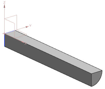
A solid geometry part is created by extruding a quarter-circle cross-section to a length of 0.1 m and a radius of 0.01 m.

Simulation model
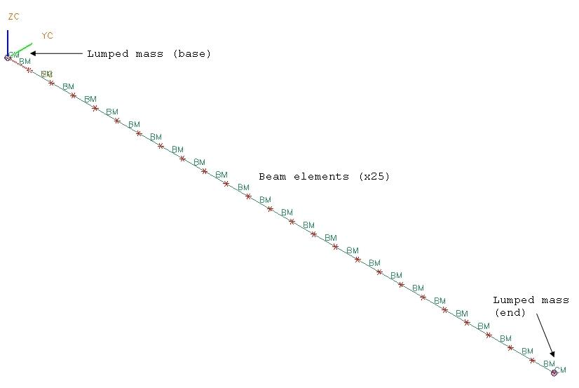
Mesh points are assigned to the ends of the straight edge of the solid geometry. A one dimensional mesh of the beam elements is then generated on that edge. 25 elements are assigned to the mesh, with each one obtaining a length of 0.004 m. In order to apply boundary conditions to the fin ends, lumped mass elements are placed at the locations of the two mesh points.

The meshed elements have the following material and physical properties:
- Material: nickel-steel
- Thermal conductivity: k =12 W/m K
- Circular cross-section with radius =0.01 m
- The lumped mass: mass = 0 and diameter d = 0 m at the base of the fin
- The lumped mass: mass = 0 and diameter d = 0.01 m at the end of the fin
- Cross-sectional fin area: A = 3.14x10⁻⁴ m2
The following boundary conditions are applied:
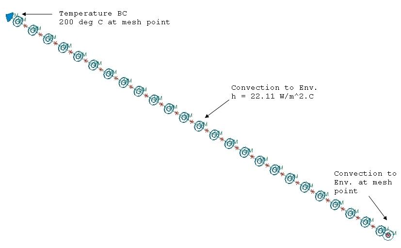
- Temperature constraint on the mesh point of the fin base with a value of Tb = 200 °C
- Convection to Environment constraint on the fin length with a heat transfer coefficient h = 22.11 W/m2°C and an ambient temperature
- Convection to Environment constraint on the mesh point at the end of the fin in order to have the convection at the tip surface

The following solution options are set:
- Solution Type=Steady State
- Results Options: select the conductive heat fluxes at nodes and elements
- Ambient Conditions: fluid temperature = 30 °C
- Initial Conditions: initial temperature = 200 °C to facilitate a convergence
The default solver parameters are selected.
Theory
This is a one-dimensional problem, since heat is conducted along the length of the fin [1]. However, at each location along that length, convection to the environment occurs due to the temperature difference between the fin and the environment. Conservation of energy for a differential slice of the fin yields the following differential equation:
where:
The solution to this differential equation is given by:
where:
The coefficients are obtained by considering the boundary conditions:
The latter requires that the conduction into the tip surface equal the convection from the tip surface. The resulting temperature distribution is given by:
while the conductive flux is defined as:
The parameters are:
Results
The following table compares the results obtained from the theoretical calculation with the following results from the thermal solver, which includes nodal temperature and elemental heat flux using finite volume, and finite element methods. The two methods of discretization, finite volume and finite element methods, give the same results, which are in agreement with the theoretical values.
| x (m) | Ttheory (°C) | Tsim (°C) | Error (%) | x (m) | q"theory (W/m2) | q"sim (W/m2) | Error (%) |
|---|---|---|---|---|---|---|---|
| 0 | 200.00 | 200.00 | 0.0 | 0.002 | 3.63E+04 | 3.63E+04 | 0.00 |
| 0.004 | 187.89 | 187.89 | 0.0 | 0.006 | 3.35E+04 | 3.35E+04 | 0.00 |
| 0.020 | 148.13 | 148.15 | 0.0 | 0.022 | 2.42E+04 | 2.42E+04 | 0.01 |
| 0.028 | 132.66 | 132.67 | 0.0 | 0.030 | 2.04E+04 | 2.04E+04 | 0.01 |
| 0.036 | 119.61 | 119.62 | 0.0 | 0.038 | 1.71E+04 | 1.71E+04 | 0.01 |
| 0.044 | 108.67 | 108.69 | 0.0 | 0.046 | 1.43E+04 | 1.43E+04 | 0.02 |
| 0.052 | 99.60 | 99.62 | 0.0 | 0.054 | 1.17E+04 | 1.17E+04 | 0.02 |
| 0.060 | 92.17 | 92.19 | 0.0 | 0.062 | 9.46E+03 | 9.46E+03 | 0.02 |
| 0.068 | 86.21 | 86.23 | 0.0 | 0.070 | 7.42E+03 | 7.42E+03 | 0.03 |
| 0.076 | 81.58 | 81.60 | 0.0 | 0.078 | 5.56E+03 | 5.56E+03 | 0.03 |
| 0.084 | 78.17 | 78.19 | 0.0 | 0.086 | 3.83E+03 | 3.83E+03 | 0.04 |
| 0.092 | 75.89 | 75.91 | 0.0 | 0.094 | 2.18E+03 | 2.19E+03 | 0.07 |
| 0.100 | 74.70 | 74.72 | 0.0 |
