VVT25 - Rotational effects on two-sided thermal stream
| Test case |
|---|
| SVTEST256 |
Description
This validation case examines rotational effects from a relative temperature frame of reference, specified for a two sided streams, which is applied to the edges of the plates with different length. This case compares the fluid temperature results computed by the thermal solver and the temperatures from the analytical solution.
Geometry
The model geometry consists of two 2D plates with the dimensions of 400 mm by 10 mm (1) and 300 mm by 10 mm (2) in the y and x directions, respectively.

Simulation model
This model uses the Simcenter 3D Multiphysics solver.
A 2D mesh is generated using axisymmetric parabolic triangle elements. The element size is 5 mm.
Plates are defined using shell material with a density of 0 kg/m3.
The following fluid material properties are used:
- Mass density: 2.35 kg/m3
- Thermal Conductivity (K): 0.02 mW/(mm·°C)
- Specific Heat (CP): 1000 J/(kg·K)
The following boundary conditions are applied:
- Two-sided Stream on Edges:
- Path Selection - Side A is the vertical edge of a plate (1) that facing the plate (2).
- Path Selection - Side B is the vertical edge of a plate (2) that facing the plate (1).
- Fluid materials is defined with the properties described above.
- Mass Flow =100 kg/s
- Inlet Temperature = 300 K
- Absolute Pressure = 0 MPa
- Rotational Effects is set to Relative Temperature Reference Frame
- Heat Transfer Coefficient = 0.1 W/(m2K) for side A
- Heat transfer on side B is the same as on the side A .
- Temperature constraint is applied on the faces of both plates with 400 K.
-
Rotation load on the whole model with the angular velocity defined in the Condition Sequence as:
Time (s) Angular velocity (rad/s) 1 1 100 1000 10000 1000
The default solution options are selected.
Theory
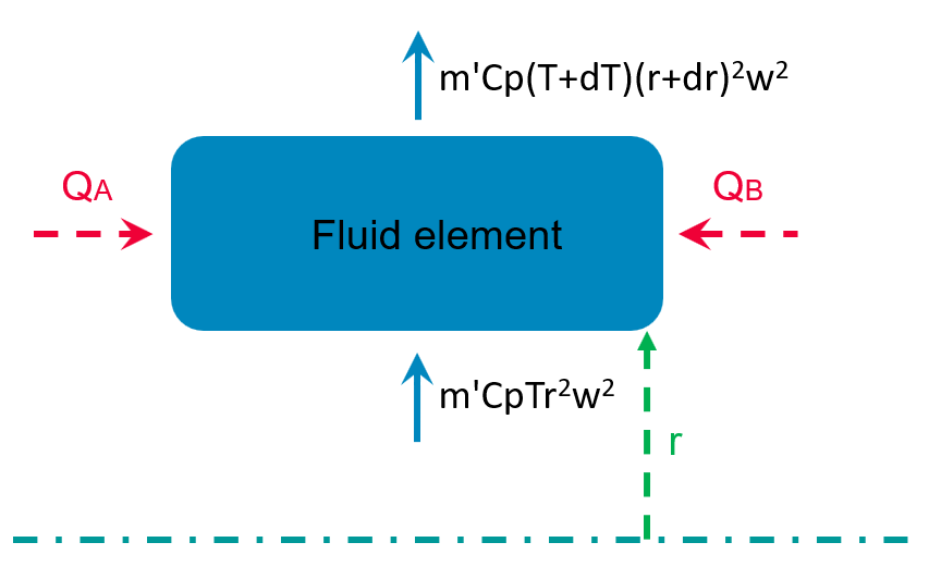
The following image explains how the energy equation is derived:

where:
- QA is the heat load from side A to the fluid element.
- h is the heat transfer coefficient.
- Tw is the wall temperature of the plates.
- TA is the temperature of the edge A.
- AA is the solid-fluid interface area between the side A and fluid element.
The solid-fluid interface area is computed as:
where:
The temperature of the side A is computes as:
Substituting rA from (121), yields:
Thus, the heat load from the side A to the fluid element is:
Similarly, the heat load from the side B to the fluid element is computed as:
From the first law of thermodynamics:
Solving differential equation:
Solving and representing the following equation with μ:
Simplify the expression by representing it as follows:
Therefore,
At r=0 and T=Ti,
where, Ti is the stream inlet temperature.
Hence,
Results
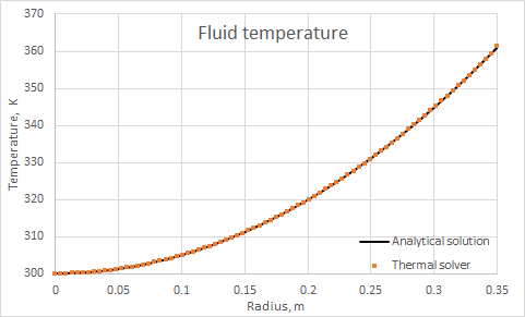
The following compares the fluid temperature, which varies with distance, computed by the solver using the finite element method and the temperatures from the analytical solution.

