VVT19 - Joule heating in an electrical wire
| Solution | Test case |
|---|---|
| Finite volume method | SVTEST24 |
| Finite element method | SVTEST250 |
Description
This validation case examines Joule heating in bare nickel-chrome wires using electrical coupling to join two disjointed meshes together within an electrical network. The wires are carrying a current and exposed to the ambient air. The test compares the centerline temperature and the wall temperature of the wires computed by the thermal solver with an analytical solution.
Geometry
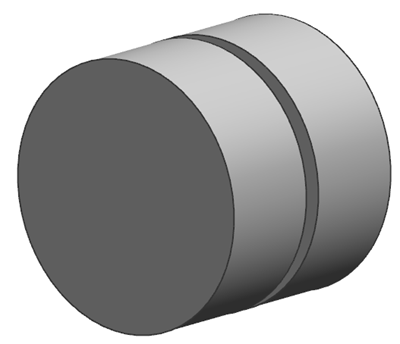
The geometry consists of two similar cylinders with a radius of r = 9.52 mm and a length of L = 7.62 mm. The distance between the cylinders is d = 1.27 mm.

Simulation model
This model uses the Advanced Thermal solution type.
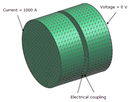
The cylinders are meshed using a tetrahedral mesh with a 1 mm elements size.
The following wire properties are used:
- Material: Nickel - chrome
- Resistivity: ρmat = 9.35114e-08 Ω·m
- Thermal conductivity: k= 22.4845 W/m·K
The following boundary conditions are applied:
- Joule Heating: Current on the base surface of the first cylinder facing the ambiance with a value of 1000 A.
- Joule Heating: Voltage on the base surface of the second cylinder facing the ambiance with a value of 0 V.
- Joule Heating: Electrical Coupling on the base surfaces of both cylinders facing each other using Conductance Gap type with electrical resistivity of 9.35114e-08 Ω·m.
- Convection to Environment on the lateral surfaces of both cylinders with a convection coefficient of 2.83723e-05 W/mm2·°C and an ambient temperature of 21.11 °C.

The default solver options are selected.
Theory
All the power generated by the cylinders must be dissipated by convection to the air:
where:
- R1 is the thermal resistance of the cylinders.
- R2 is the thermal resistance of the gap between cylinders.
- I is the current.
- h is the convection coefficient.
- A is the lateral surface area of the cylinders.
- Tw is the wall temperature.
- Tamb is the ambient temperature.
The thermal resistance of the two cylinders R1 is computed as follows:
where:
- ρmat is the resistivity of the material.
- L is the length of each cylinder.
- r is the radius of the cylinder.
The thermal resistance of the gap R2 is computed as follows:
where:
- ρgap is the resistivity of the gap.
- d is the distance between two cylinders.
The wall temperature Tw is defined as:
while the centerline temperature To is calculated by the following equation:
where:
- To is the centerline temperature at r = 0.
- is the heat generated per unit volume.
- k is the thermal conductivity of the cylinder.
The heat generated per unit volume is calculated as follows:
Solving the equation for centerline temperature gives:
Results
The following table compares the wall and centerline temperatures computed by the thermal solver with the analytical solution:
| Finite volume method | Finite element method | ||||
|---|---|---|---|---|---|
| Parameter | Ttheory (°C) | Tsim (°C) | Error (%) | Tsim (°C) | Error (%) |
| Tw | 230.86 | 230.86 | 0 | 230.867 | 0.003 |
| To | 232.12 | 232.27 | 0.06 | 232.123 | 0.001 |
