VVT22 - Rotational effects on thermal void
| Solution | Test case | ||
|---|---|---|---|
| Finite volume method | Case A: Correct for Wall Rotation | SVTEST222 | |
| Case B: Relative Temperature Reference Frame | SVTEST223 | ||
| Finite element method | Case A: Correct for Wall Rotation | SVTEST252 | |
| Case B: Relative Temperature Reference Frame | SVTEST253 | ||
Description
This validation case examines the following two cases that concern different types of rotational effects specified for a thermal void, which is applied to two edges of a rotating model.
Case A: The rotational effects option is set to Correct for Wall Rotation. The fluid temperature is assumed to be the absolute total temperature.
Case B: The rotational effects option is set to Relative Temperature Reference Frame. The fluid temperature is assumed to be the relative total temperature.
For each rotational effects type, the steady-state temperature results predicted by the solver are compared to those from the analytical solution.
Geometry
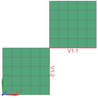
The model geometry contains two 10 mm square plates that rotate about the XC axis.
Simulation model
A 2D mesh is generated using parabolic quadrilateral elements that are 2 mm in size.

The meshed elements have the following material and physical properties:
Shell material for plates: Aluminum_2014
- Mass density: ρ = 2794 kg/m3
- Thermal Expansion Coefficient: A = 2.16e-5 (°C)-1
- Thermal conductivity: K = 154.25 W/m-°C
- Specific heat at constant pressure: Cp = 880 J/kg-K
Environmental fluid material : Air
- Mass density: ρ = 1.2041 kg/m3
- Specific heat at constant temperature: Cp = 1007 J/kg-K
The following boundary conditions are applied:
- Thermal Void:
- Region1 is the right vertical edge of square 1 (radius changes from 0 to 10mm).
- Region 2 is the bottom horizontal edge of square 2 (radius of 10mm).
- No heat load is applied.
- The environment fluid material is set to Air.
- The area of internal edges set to Add Thickness.
- In case A:
- The rotational effects option is set to Correct for Wall Rotation for both regions.
- The heat transfer coefficient = to 0.01 W/mm2·°C for both regions.
- In case B:
- The rotational effects option is set to Relative Temperature Reference Frame for both regions.
- The heat transfer coefficient = 0.01 W/mm2·°C for the horizontal edge and 0.02 W/mm2·°C for the vertical edge.
- Temperature constraint on horizontal edge is 50 °C and on the vertical edge is 70 °C.
- Rotation load on the whole model with the angular velocity w=1000 rad/s is about the XC axis.
The following solution options are set:
-
The Advanced Thermal solution type is selected.
-
The default solver parameters are selected.
-
Total Temperature is selected as a requested thermal results option.
Theory
The void fluid temperature is defined by solving the energy equation for a thermal void. The thermal void represents a volume of fluid with constant equilibrium temperature at any time, that convects with surrounding metal. The energy equation is given by:
where:
- j=1,2,…,N represents the metal elements surfaces in contact with the void fluid at its boundaries.
- Tt,rel is the total relative fluid temperature.
- Ts is the metal temperature at the edge.
- hj is the specified local heat transfer coefficient.
- Aj is the solid-fluid interface area.
- Q is the power input into the void.
- ρ is the density of the fluid material in the void cavity.
- V is the volume of the void cavity.
- Cp is the specific heat of the fluid material in the void cavity.
Case A
For this case, the fluid temperature is assumed to be the absolute total temperature. The energy equation is simplified to:
The total absolute fluid temperature is calculated by solving the following equation:
where the relative temperature difference is given by the following equation:
For the vertical edge:
For the horizontal edge:
The total absolute fluid temperature is calculated by solving the following equation:
The total relative fluid temperature on the horizontal edge is calculated as:
Case B
For this case, the fluid temperature is assumed to be the relative total temperature. The energy equation is simplified as:
The total relative fluid temperature is calculated from the following equation:
The total absolute fluid temperature is then calculated as follows:
at radius = 0 mm:
at radius = 10 mm:
where:
Results
The following table compares the void total and relative absolute fluid temperature that is calculated by the thermal solver with the analytical solution.
| Finite volume method | Finite element method | |||||
|---|---|---|---|---|---|---|
| Case | Parameter | Ttheory (°C) | Tsim (°C) | Error (%) | Tsim (°C) | Error (%) |
| A | Tt,abs | 59.9690 | 59.9670 | 0.003 | 59.967 | 0.003 |
| Tt,rel at radius = 0 mm | 59.9690 | 59.9675 | 0.003 | 59.968 | 0.002 | |
| Tt,rel at radius = 10 mm | 60.0186 | 60.0166 | 0.003 | 60.016 | 0.004 | |
| B | Tt,rel | 63.3333 | 63.3333 | 0 | 63.333 | 0.000 |
| Tt,abs at radius = 0 mm | 63.3333 | 63.3328 | 0.0008 | 63.332 | 0.002 | |
| Tt,abs at radius = 10 mm | 63.2836 | 63.2837 | 0.00008 | 63.284 | 0.000 | |
