VVT34 - Two streams on the same edge selection
| Test case |
|---|
| SVTEST269 |
Description
The purpose of this validation test is to verify the accuracy of convective flux and other heat transfer parameters when two thermal streams are applied to the same selection. This test ensures that the thermal solver correctly simulates the interactions and heat transfer dynamics between the two thermal streams.
Geometry
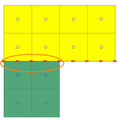
The model geometry consists of two attached 2D plates with dimensions of 20 by 10 mm and 10 by 10 mm and a thickness of 1.5 mm.
Simulation model
Two 2D meshes are generated using linear quadrilateral elements for two plates with a size of 5 mm.

The meshed elements have the following material and physical properties:
- Shell material for the plates: Steel
- Mass density: ρ = 7829 kg/m3
- Environmental fluid material: Air
- Mass density: ρ = 1.2041 kg/m3
- Specific heat at constant temperature: Cp = 1004.5 J/kg·K
The following boundary conditions are applied:
- The Temperature constraints on both plates of 20°C.
- The Whole Model type of the Rotation load with the angular velocity of 10000 rad/s.
- The One-Sided Stream on Edges type of the
Thermal Stream 2 simulation object on the edge of the
bigger plate with the following options:
- Mass Flow = 1 kg/s
- Inlet Temperature = 50 °C
- Absolute Pressure = 1 MPa
- Area for Internal Edges = Add Thickness
- Area Correction Factor = 2
- Heat Transfer Coefficient = 0.1 W/(mm2·°C)
- Heat Pickup = 0.1 W/mm2
- Swirl Velocity = 100 mm/s
-
One-Sided Stream on Edges type of the Thermal
Stream 1 simulation object on the edge of the smaller plate with
the following options:
- Mass Flow = 2 kg/s
- Inlet Temperature = 40 °C
- Absolute Pressure = 2 MPa
- Area for Internal Edges = Add Thickness
- Area Correction Factor = 3
- Heat Transfer Coefficient = 0.2 W/(mm2·°C)
- Heat Pickup = 0.2 W/mm2
- Swirl Velocity = 200 mm/s
The following image shows the thermal stream overlapping area.

This model uses the Simcenter 3D Multiphysics solver.
The default solver parameters are selected.
Theory
The total fluid temperature is calculated for the selection with multiple boundary conditions applied as follows.
where:
- h is the specified heat transfer coefficient in the thermal streams.
- C is the area correction factor.
- T is the inlet temperature of the thermal streams.
The heat transfer coefficient is the sum of the heat transfer coefficients from the contributing boundary conditions:
The corrected heat transfer coefficient is the sum of the area corrected heat transfer coefficients from the contributing boundary conditions:
Fluid pressure on the wall is the maximum pressure.
The total convective heat flux contribution from each boundary condition is the sum of the heat flux from all overlapping boundary conditions:
where Ta is the ambient fluid temperature.
The total fluid swirl velocity:
Results
The following table compares the results predicted by the thermal solver with the calculated theoretical results. Simulation results are in agreement with theoretical values.
| Parameter | Theory | Simulation | Error (%) |
|---|---|---|---|
| Tftotal (°C) | 42.5 | 42.48 | 0.04 |
| htotal (W/mm2·°C) | 0.3 | 0.3 | 0 |
| hcorrected (W/mm2·°C) | 0.8 | 0.8 | 0 |
| Ptotal (MPa) | 1.75 | 1.75 | 0 |
| qtotal W/mm2 | 18 | 17.98 | 0.11 |
| υϕtotal mm/s | 175 | 175 | 0 |
