VVT6 - Hollow sphere with two materials and convective boundary conditions
| Solution | Test case |
|---|---|
| Finite volume method | SVTEST7 |
| Finite element method | SVTEST233 |
Description
The purpose of this test case is to determine the inner material boundary and outer surface temperatures of a hollow sphere which is convecting from both the inner and outer surfaces.
Geometry
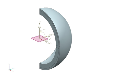
The solid geometry was created by revolving the sketch of half an annulus through an angle of 90 degrees. The inner radius of the annulus is ri = 300 mm, while the outer radius is ro = 370 mm. The result is a quarter hollow sphere. A surface to represent the material boundary was created by revolving the sketch of an arc through an angle of 90 degrees, with a radius of rm = 350 mm. In addition, two datum planes were created by rotating copies of the XY plane ±2.5 degrees about the y-axis. The result is shown in the following figure. The front face of the quarter sphere was subdivided using the referencing the revolved surface and the two datum planes. This created a representative slice of the hollow sphere, with an edge at the material boundary.

Simulation model
This model uses the Axisymmetric Thermal solution type.
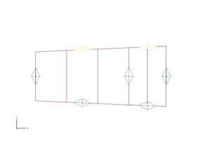
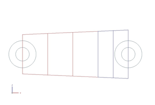
The mesh is made of quadrilateral axisymmetric ZX shells using the mesh controls to the edges in order to generate five elements: three for the inner material and two for the outer material. The following figure shows that the elements are not the same size, but increase with radial distance.

The meshed elements have the following material and physical properties:
- Thermal conductivity: ki = 40.0 W/m·°C to the inner mesh.
- Thermal conductivity: ki = 20.0 W/m·°C to the outer mesh.
- Mass density: arbitrary (both meshes) as this has no bearing on the analysis results.
The following boundary conditions are applied:
- Convection to Environment constraint on the inner edge of the mesh with a heat transfer coefficient hi = 150 W/m2·°C and an ambient temperature Ti,∞ = 70 °C.
-
Convection to Environment constraint on the outer edge of the mesh with a heat transfer coefficient ho = 200 W/m2·°C and an ambient temperature To,∞=−9 °C.

The following solution options are set:
- Solution Type =Steady State
- Results Options: Select the conductive heat fluxes at nodes and elements.
The default solver parameters are selected.
Theory
Solving the heat equation expressed in spherical coordinates shows that the temperature within the solid material of the sphere is inversely proportionate to the radial location. The heat flow in the radial direction is constant. As such, this system can be viewed as a series network of thermal resistances between the ambient temperature within the hollow sphere and that outside the sphere. The thermal resistances due to convection within the sphere, due to conduction through the two materials of the sphere, and due to convection outside the sphere are, respectively:
Then, the heat flow in the radial direction is given by:
The temperature at the inner, material boundary, and outer surfaces of the hollow sphere are defined as:
Results
The following table compares the nodal temperature results at the inner, material boundary, and outer surfaces, predicted by the thermal solver, with the calculated theoretical results. Simulation results are in agreement with theoretical values.
| Parameter | Ttheory (°C) | TFV (°C) | ErrorFV (%) | TFE (°C) | ErrorFE (%) |
|---|---|---|---|---|---|
| Ti | 25.06 | 24.97 | 0.36 | 25.052 | 0.032 |
| Tm | 17.84 | 17.81 | 0.17 | 17.842 | 0.011 |
| To | 13.15 | 13.16 | 0.08 | 13.16 | 0.076 |
The table below shows the radial heat transfer rate, qr, obtained from the elemental heat fluxes calculated by the thermal solver. It is nearly constant, and is comparable with the theoretical value.
| r (m) | qr",FV (W/m2) | qr,FV (W) | Error FV (%) | qr",FE (W/m2) | qr,FE (W) | ErrorFE (%) |
|---|---|---|---|---|---|---|
| 0.308 | 6.383 × 10³ | 7.611 × 10³ | 0.28 | 6.381 × 10³ | 7.609 × 10³ | 0.31 |
| 0.324 | 5.744 × 10³ | 7.610 × 10³ | 0.29 | 5.743 × 10³ | 7.690 × 10³ | 0.31 |
| 0.341 | 5.196 × 10³ | 7.608 × 10³ | 0.32 | 5.197 × 10³ | 7.609 × 10³ | 0.30 |
| 0.354 | 4.807 × 10³ | 7.599 × 10³ | 0.44 | 4.814 × 10³ | 7.610 × 10³ | 0.29 |
| 0.364 | 4.548 × 10³ | 7.599 × 10³ | 0.44 | 4.554 × 10³ | 7.610 × 10³ | 0.29 |
