VVT35 - Transient temperature with a PID controller
| Solution | Test case |
|---|---|
| Case A | SVTEST270 |
| Case B | SVTEST271 |
Description
The purpose of this verification test is to verify how a PID controller maintains a set point temperature over time by adjusting control inputs. The test compares the results with the analytical solution for two cases:
- Case A: The load is defined with proportional and integral terms.
- Case B: The load is defined with proportional, integral, and derivative terms.
Simulation model
The model consists of one 2D element generated using a thin shell with a size of 0.13 mm and thickness of 100 mm.

The meshed elements have the following material and physical properties:
- Shell material for the plate with:
- Mass density: ρ = 1000 kg/m3
- Thermal conductivity k = 1 W/(m·K)
- Specific heat: cp = 2.5 J/(kg·K)
- Environmental fluid material: Air
- Mass density: ρ = 1.2041 kg/m3
- Specific heat at a constant temperature: Cp = 1004.5 J/kg·K
The following boundary conditions are applied:
- The Convection to Environment constraint to convect from the top and bottom with a convection coefficient hi = 50 W/m2◦C and a fluid ambient temperature of 20 °C.
- The Heat Load type of Thermal Loads with a heat load of 100 W with the defined active heater controller.
- The Active Heater Controller modeling object with the PID Controller type. The following table describes the parameters used for test cases A and B.
| Parameter | Case A | Case B |
|---|---|---|
| Set Point Temperature | 100 °C | 100 °C |
| Gain | 0.315 | 0.140 |
| Integral Term Constant | 0.01134 | 0.00373 |
| Derivative Term Constant | 0 | 0.1407 |
| Bias | 0 | 0 |
This model uses the Simcenter 3D Space Systems Thermal environment.
The following solution options are set:
- Solution Type = Transient
- Fluid Temperature = 20 °C
- Integration Method = Implicit, because the model has an active heater controller that oscillate fast and have large time steps
- Time Step = 1
- End Time = 500 s
The default solver parameters are selected.
Theory
The energy balance on the element for a temperature control process involving a PID controller is given by:
where:
- C is the heat capacity of the system.
- G is the thermal conductance between the system and the environment.
- Tenc is the ambient temperature.
- Qin is the heat input, which is controlled by the PID controller.
The PID controller inputs the load according to the following relationship.

where:
-
Set Point Temperature is the target temperature Ts that you define. This temperature is used to calculate the error e(t)=Ts-Telement(t), where Telement(t) is the temperature of a given element at time t.
-
Kp is the proportional gain parameter.
-
KI is the integral gain parameter.
-
Ke is the derivative gain parameter.
-
e(t) is the error function over time.
-
Offset is the bias.
Results
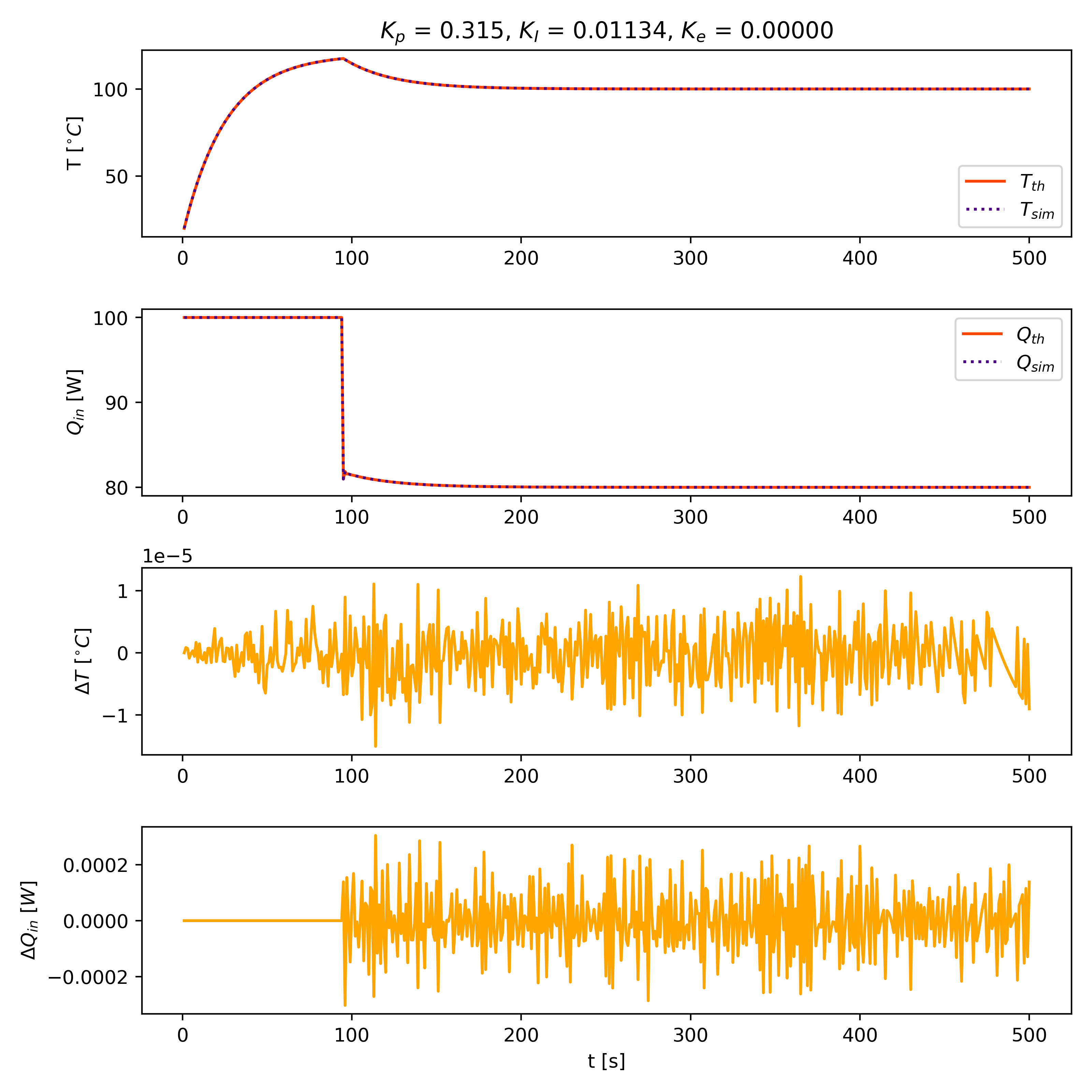
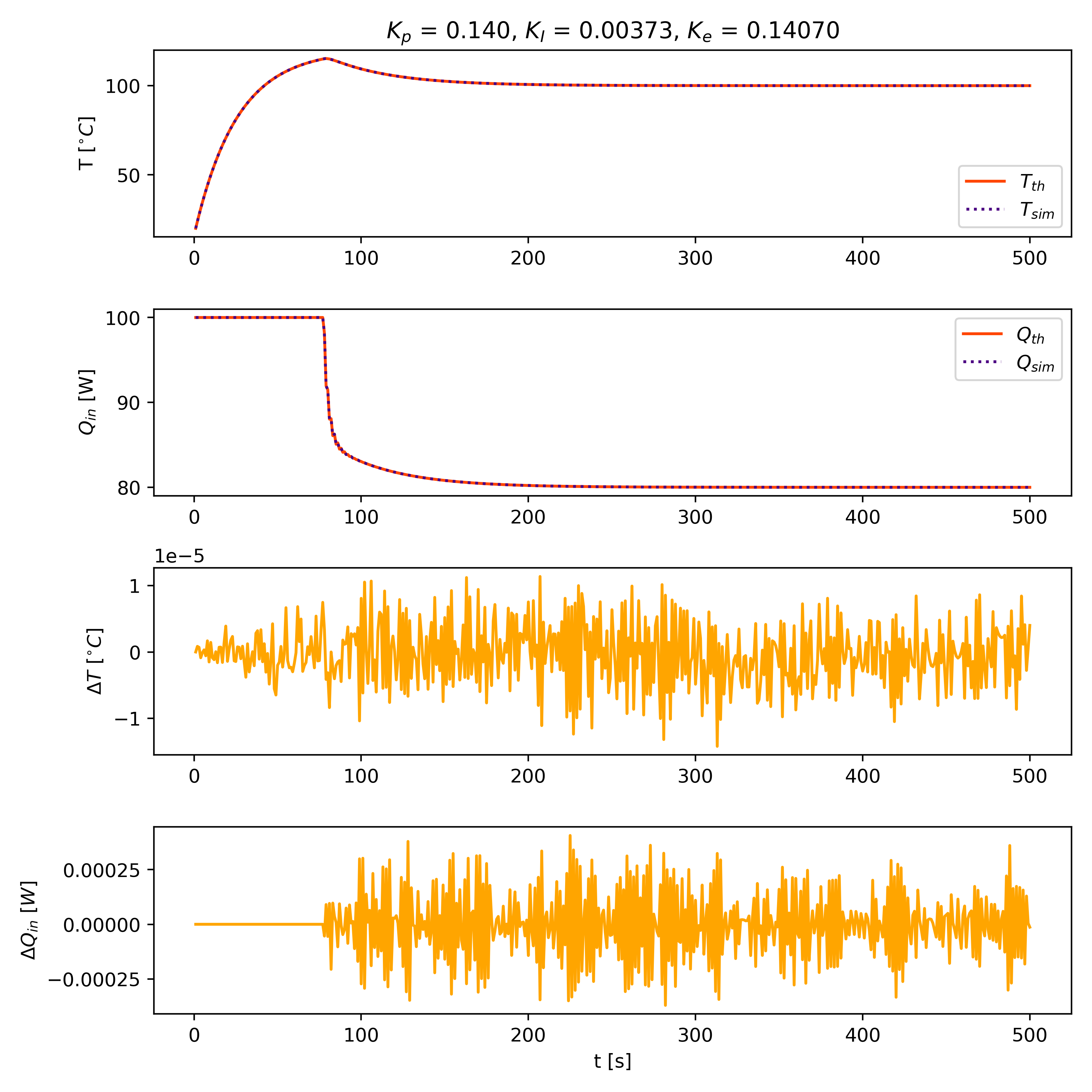
The following graphs compare the results predicted by the thermal solver with the calculated theoretical results. The simulation results are in agreement with the theoretical calculations. The graphs, from top to bottom, display:
- Temperatures from both simulation and theoretical calculations. The PID controller maintains a set point temperature of 100 °C.
- Power Qin from both simulation and theoretical calculations.
- Temperature differences between simulation and theoretical results.
- Power differences between simulation and theoretical results.
| Case A | Case B |
 |
 |
