Defining thermal streams
This topic explains how to define and use Thermal Streams to model convective heat transfer, including setup, required inputs, stream types, governing equations, and advanced options for accurate modeling.
This lesson may include hands-on exercises. Review the Discussion section for background information or click the button to proceed to the practical section.
Discussion
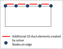
Use the Thermal Stream load to define convection caused by fluid flow over surfaces or along axisymmetric edges. The thermal solver automatically creates a 1D duct with mass flow elements on the selected regions and connects them to the nearest thermal solid elements through convective coupling.
- Using thermal streams
- Thermal streams provide a simplified approach for modeling flowing fluids in
thermal analyses. Thermal streams:
- Model an air stream with defined inlet conditions and known flow direction.
- Do not require explicit creation of a fluid network.
To define a thermal stream, specify:
- Inlet temperature that can be time-dependent.
- Mass flow rate that can be time- or space-dependent.
- Heat transfer coefficient (HTC) to the surrounding metal.
- (Optional) Heat pickup term to add an additional heat source to the flowing stream.
The temperature rise of the stream depends on its specific heat, convection with the solid, and any heat pickup.
When defining thermal streams, you can:
- Specify flow reversal conditions to handle changes in flow direction during the solution.
- Control convective area correction to define how the solver adjusts the effective heat transfer area. Use this option to verify that your model setup produces physically consistent results.
- Account for rotational effects.
If you apply a Rotation load and enable Correct for Wall Rotation, the solver corrects the inlet temperature based on the specified Swirl Ratio or Swirl Velocity. For more information, see Relative temperature effects.
- Thermal stream energy equation
- The energy equation for a one-sided thermal stream is:
Where:
- is the specified mass flow rate of the stream.
- is the specific heat of the stream fluid material.
- is the fluid temperature computed by the thermal solver.
- is the solid body temperature that convects with the stream and is computed by the solver.
- is the area of the solid body associated with the stream as computed by the thermal solver.
- is the heat transfer coefficient between the fluid and solid surface.
- is the optional heat pickup associated with the current element (per unit area).
You can define thermal streams using proprietary correlations stored in a DLL file referenced in the Custom Plugin customer defaults.
- Types of thermal streams
- Thermal streams can be defined on edges or surfaces using the following
types:
- Two-Sided Stream on Edges and Faces
- Two-Sided Stream on Edges
- One-Sided Stream on Faces
- One-Sided Stream on Edges
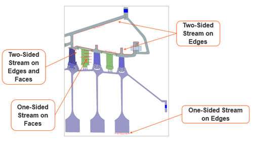
Select the appropriate type based on how the fluid interacts with the geometry and whether heat exchange occurs on one or both sides.
- Thermal streams on edges
- Use Path Selection to define a thermal stream along
edges.
Select a start point and an end point on the surface to automatically include all edges in between. You do not need to split or modify the CAD geometry.
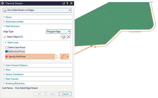 Tip:To prevent streams from jumping across multiple components, clear Jump Edge Gaps in the Smart Selector Options dialog box.
 - Thermal streams on faces
- Define a vector to specify the flow direction. The vector does not need to
be exact. As long as it is not perpendicular to the initial face, the flow
direction follows the curvature of the selected geometry.
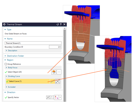
Use the Dividing Curve option to apply the boundary condition only to part of the faces on one side of a selected curve.
Hands-on material
To gain experience with the topics discussed here, complete the following: