Preparing geometry for WEM
This topic explains why geometry preparation is critical for WEM analysis. You will learn how to simplify 3D CAD geometry into efficient 2D or hybrid models and how to prepare geometry for meshing and simulation in Simcenter 3D.
This lesson may include hands-on exercises. Review the Discussion section for background information or click the button to proceed to the practical section.
Discussion
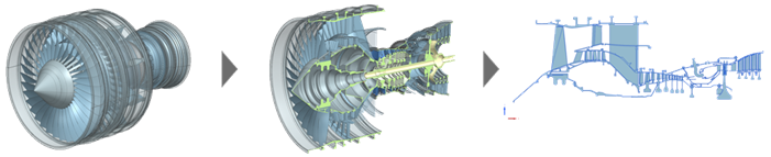
WEM simulates the transient thermal and structural behavior of major engine components. Because a full 3D representation of the engine is not computationally feasible, you simplify the geometry into 2D or hybrid 2D–3D models.
You can model:
- Axisymmetric components using 2D axisymmetric elements.
- Non-axisymmetric components using plane stress or 3D elements.
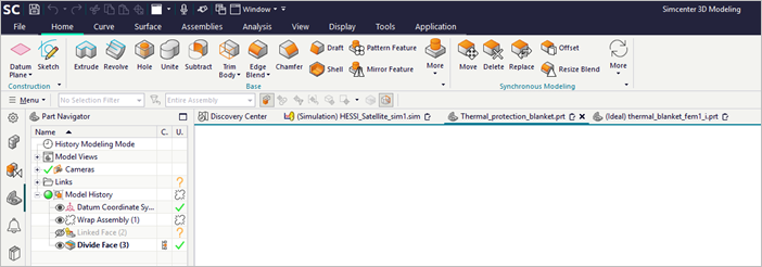
Each subassembly is extracted from the full 3D CAD model and remains associated with it. This associative workflow ensures that any design changes automatically propagate to the analysis model.
You can create geometry manually using sketch-based modeling or import it from third-party CAD systems.
- Sketch-based modeling
- A sketch is a named set of 2D curves defined on a plane or path. Use
Sketch to:
- Define profiles or typical cross-sections.
- Create detailed part features by sweeping, extruding, or revolving a sketch into a solid or a sheet body.
- Develop large-scale 2D layouts with hundreds or even thousands of sketch curves.
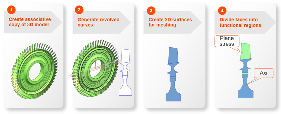
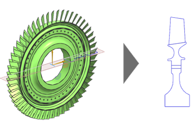
- Idealizing 3D geometry into 2D
- To create a 2D representation of the engine:
- Create an associative copy of the 3D model.
- Generate revolved curves.
- Create 2D surfaces for meshing.
- Divide faces into functional regions.
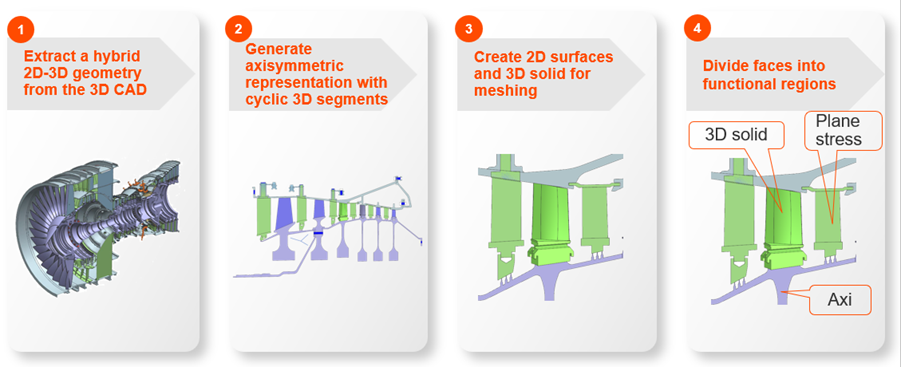
- Idealizing 3D geometry into a hybrid 2D–3D model
- For components that require more detailed representation, you can use a
hybrid approach:
- Extract a hybrid 2D-3D representation from the 3D CAD model.
- Generate an axisymmetric representation with cyclic 3D segments.
- Create 2D surfaces and 3D solids for meshing.
- Divide faces into functional regions.
- Creating an associative copy of geometry
- Before modifying an idealized part, you must first create an associative
copy of the geometry you want to modify, using:
- Promote, which copies selected solid or sheet bodies.
- WAVE Geometry Linker, which creates associative links to bodies, faces, or edges.
Use WAVE Geometry Linker for greater control over which geometry is copied and when updates are applied.
- Creating 2D cross section curves from a 3D component
- Use the Revolve Outline command to project 3D
geometry onto an axisymmetric plane.
The system generates outlines based on a specified rotation axis and creates curve geometry that defines the 2D skeleton used for analysis.
This process captures:
- Axisymmetric features such as casings, disks, and hubs.
- Plane stress features such as blades, holes, stiffeners, and bosses.
- Creating and dividing surfaces
- To create or add surfaces, use:
- Bounded Plane, which creates a planar sheet body enclosed by a set of end-connected planar curves.
- N-Sided Surface, which creates a surface enclosed by a set of end-connected curves.
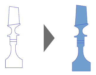
Use these commands to repair holes or reconstruct missing geometry before idealization. Each closed curve loop defines a surface suitable for 2D mesh generation.
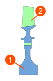
Use Divide Face to divide one or more faces of an existing body using multiple dividing objects, such as curves, edges, faces, datum planes, and solid bodies. Create separate faces for:
- Axisymmetric regions (1).
- Plane-stress regions (2), such as blade paths and cooling-hole zones.
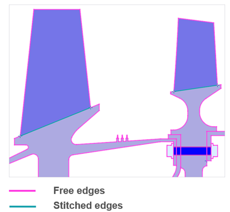
- Ensuring mesh connectivity
- Check for free or unconnected edges using Element
Edges.
To repair geometry, use:
- Stitch Edge, which stitches together free edges within a solid or sheet body or across different bodies.
- Merge Edge, which removes unnecessary splits.
- Sew, which joins surfaces into a single body.
Hands-on material
To gain experience with the topics discussed here, complete the following: