Cyclic Symmetry
This topic explains how to use Cyclic Symmetry in turbomachinery thermal models.
This lesson may include hands-on exercises. Review the Discussion section for background information or click the button to proceed to the practical section.
Discussion
Use Cyclic Symmetry to represent a full 360-degree rotational system by modeling only a single sector of the geometry. This approach significantly reduces model size and computational cost while preserving the thermal and structural behavior of repeating engine segments.
The thermal and structural solvers use boundary coupling to create periodic coupling conditions between sector faces. The coupling occurs between source and target region nodes located within a specified search distance using a weighted-area method.
- Cyclic symmetry capabilities
- For conduction, convection, and radiation calculations, the thermal solver
does not physically expand the modeled cyclic sector into a complete
360-degree model. Instead, it scales the computed quantities to represent
the full geometry.
The cyclic symmetry definition:
- Applies rotational periodic boundary conditions for thermal sector models.
- Reduces solve time and model size compared to full 3D models.
- Automatically scales convecting areas, thermal conductivity, and specific heat to represent the correct number of engine sectors.
The thermal solver uses the following information to create cyclic coupling:
- Axis of revolution.
- Coupling resolution.
- Overlap settings.
To ensure physically meaningful results, you must correctly define:
- Cyclic interface regions.
- Coordinate systems.
- Stage assignments.
For more accurate radiation modeling, especially when radiation occurs between neighboring sectors, you can select Enable Radiative Thermal Rotational Periodicity.
- Using cyclic symmetry for material properties and area scaling
- To ensure correct scaling behavior, you must properly define the cyclic
interface regions, coordinate system, and stage assignments.
Select the source and target regions that define the cyclic interface.
When using cyclic symmetry in a hybrid 2D/3D model:
- Exclude faces located at the 2D/3D interface.
- Avoid applying both cyclic boundary conditions and nodal coupling to the same interface.
Otherwise, the model may become over-constrained.
Defining the coordinate systemSelect the global cylindrical coordinate system if it is not already defined in the FEM file.
The selected coordinate system must:
- Be cylindrical.
- Have a Z-axis collinear with the cyclic-analysis axis of revolution.
Use Calculate Segment to determine the periodic sector relationship automatically.
Verify that the computed Number of Segments matches the intended engine periodicity.
Sometimes the software cannot automatically determine the number of cyclic sectors. This issue can occur due to:
- Twisted or misaligned cut geometry.
- Improper distance or angle tolerances.
- Non-periodic geometry.
If the calculation fails:
- Use Swap Regions.
- Increase the distance tolerance up to 1 mm.
- Adjust the angle tolerance.
- Verify the cyclic interface geometry.
- Check periodicity.
You can use measurement tools to verify that arcs are centered at the engine axis (radius = 0), and that the geometry is radially consistent.
- Realign the geometry or break it into smaller sectors.
In the Stages group, select the mesh elements that belong to the cyclic sector and assign the appropriate stage number.
The solver uses the stage definition to correctly scale:
- Surface area.
- Thermal conductivity.
- Specific heat.
- Thermal mass.
- Energy quantities.
If no elements are selected, periodic temperature will still be applied, but the area, conductivity, and specific heat scaling will be incorrect.
- Common issues and troubleshooting
-
- If two regions have a different number of sectors, assign each region to a separate cyclic symmetry object. This ensures proper meshing and transformation across cyclic interfaces.
- If the number of sectors differs between regions, assign a unique stage number to each region. This identifier is used for postprocessing structural results and has no effect on thermal-only solutions.
- If the message The angle must be between 0 and 180 degrees appears while defining the cyclic sector, switch the source and target selection to resolve the issue.
- Check the BC Data Tables or BC data plot to verify cyclic expansion based on primary and convective area.
- Check the <simulation name>-<solution name>_report.log file to confirm cyclic expansion of elements based on mass.
- Use structural results to visually inspect cyclic expansion in the model.
- Verifying cyclic expansion using BC summary table
- You can verify that the solver correctly considers the cyclic effect for
convective boundary conditions between cyclic symmetric components.
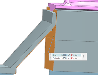
In the following example, the blade component has 69 instances around the axis of rotation. You can measure the convective region of a single instance using the measuring tool. The expected expanded convective area is A=69*0.0348 m2= 2.4 m2.
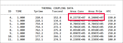
From the Thermal Coupling Area table in the BC summary table, you can verify that the thermal solver considers the cyclic effect correctly by checking Area Conv and Area Prim data to match the expected area as shown.
Hands-on material
To gain experience with the topics discussed here, complete the following: