How to model flow recirculation using thermal streams?
This article explains how to model flow recirculation between the stator and the rotor, and how to model flow splitting from the rotor stream outlet, where part of the flow leaks over the rotor surface while the remainder recirculates across the stator stream.
Introduction
In turbomachinery applications, flow recirculation occurs when a portion of the fluid reverses direction and moves upstream within the system. It is typically caused by adverse pressure gradients, flow separation, or off-design operating conditions. Factors such as blade geometry and abrupt changes in flow area can contribute. Recirculation can lead to reduced efficiency, increased mechanical stress, and potentially unstable operation, making it important to address during design and analysis.
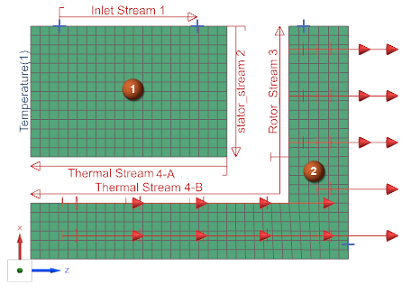
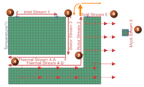
The model used for this explanation includes a stationary component (1) and a rotating component (2). Flow through the duct is modeled using thermal streams. The rotating component rotates with an angular velocity of 377 rad/s, and the stationary part is held at a fixed temperature of 500°C.
Modeling flow recirculation between the stator and the rotor
This example demonstrates how to model flow recirculation due to rotor pumping. In this case, 25% of the flow from the stator stream (2) reverses direction, while the remaining 75% combines with the thermal stream (4). The inlet stream (1) provides a total mass flow of 0.75 kg/s at 50 ° and does not interact thermally with the wall, HTC equal to 0. It mixes with the rotor stream (3) to define the inlet temperature for the stator stream (2). The stator stream (2), in turn, sets the inlet temperatures for both the rotor stream (3) and thermal stream (4).
The following table lists the options for the thermal streams required to model this case.
| Options | Inlet Stream 1 | Stator Stream 2 | Rotor Stream 3 | Thermal Stream 4 (Side A and B) |
|---|---|---|---|---|
| Type | One-Sided Stream on Edges | One-Sided Stream on Edges | One-Sided Stream on Edges | Two-Sided Stream on Edges |
| Mass Flow | 0.075 kg/s | 0.1 kg/s |
0.25*SMO(2) kg/s 25% of stator stream outlet mass flow |
SMO(2)-SMO(3) kg/s The difference in mass flow between stator and rotor streams |
| Inlet Temperature | 50 °C |
mix(3,1) The temperature from mixing the inlet and rotor stream temperatures. |
STO(2) Stator stream outlet temperature |
STO(2) Stator stream outlet temperature |
| Absolute Pressure | 0.1 MPa | 0.1 MPa | 0.1 MPa |
SP(2) Outlet pressure of the stator stream |
| Heat Transfer Coefficient | 1e-6 W/(m2·°C) | 200 W/(m2·°C) | 200 W/(m2·°C) | 200 W/(m2·°C) |
SMO(i) — Returns the outlet nodal mass flow that is defined on the stream elements.
STO(i) — Returns the stream total absolute or relative outlet nodal temperature.
SP(i) — Returns the outlet pressure of the stream in both nominal and flow reversal cases.
(i) is the boundary condition ID of the stream.
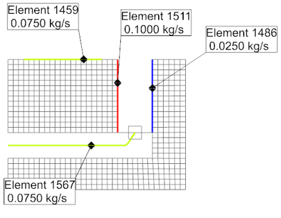
The mass flow results highlight the recirculation region, where the rotor's mass flow (blue) moves in the opposite direction and has a lower magnitude compared to the stator's mass flow (red).
Modeling recirculation with flow splitting at outlet
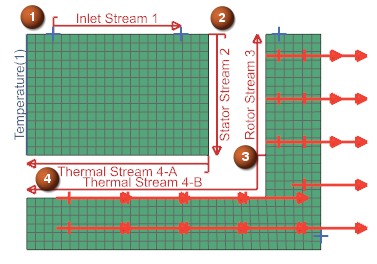
This example demonstrates recirculation with flow splitting at the outlet, where 50% of the flow on the rotor side leaks over the rotor surface and the rest recirculates into the stator stream (2). A mock stream (5) is introduced to support the calculation of mass flow and inlet temperature within the stator stream. The mock stream (5) is used as the splitting flow portion of the rotor stream (3), feeding back to the stator stream (2). The mock thermal stream must be defined on a separate mock 2D mesh.
The inlet stream (1), rotor stream (3) and resulting thermal stream (4) are defined as in the first example. The following table lists the thermal stream options required for the stator stream (2), mock stream (5), and split stream (6) to model this case.
| Options | Stator Stream 2 | Mock Stream 5 | Split Stream 6 |
|---|---|---|---|
| Type | One-Sided Stream on Edges | One-Sided Stream on Edges | One-Sided Stream on Edges |
| Mass Flow |
SMO(1)+SMO(5) Sum of inlet stream and mock outlet mass flow |
SMO(3)-SMO(6) kg/s Difference in mass flow between rotor and split streams |
0.5*SMO(3) kg/s |
| Inlet Temperature |
mix(1,5) Temperature from mixing the inlet and mock stream temperatures. |
STO(3) Rotor stream outlet temperature |
STO(3) Rotor stream outlet temperature |
| Absolute Pressure | 0.1 MPa |
SP(3) Outlet pressure of the rotor stream |
SP(3) Outlet pressure of the rotor stream |
| Heat Transfer Coefficient | 200 W/(m2·°C) | 1e-6 W/(m2·°C) | 100 W/(m2·°C) |
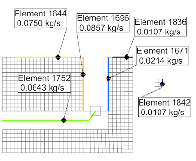
The mass flow results reveal a recirculation zone between the rotor and stator regions, along with 50% of the mass flow leaking from the rotor stream over the rotor surface.