Connecting thermal streams
This topic explains how to connect thermal streams.
This lesson may include hands-on exercises. Review the Discussion section for background information or click the button to proceed to the practical section.
Discussion
- Built-in functions such as STO, SMO and similar thermal-flow functions, which return outlet flow properties from other streams. These functions allow you to transfer flow conditions between connected streams.
- Auto-connect options to connect streams that are geometrically in contact with each other.
- The Junction simulation object to manually set up connections.
- Connecting thermal streams using the built-in functions
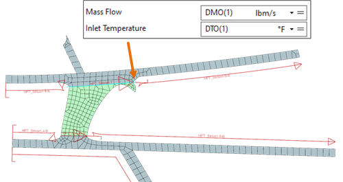
- You can connect thermal streams by defining stream properties such as mass
flow and temperature using built-in functions.
To specify stream properties, use:
- Thermal functions:
- STO(i) is the outlet temperature of stream i.
- SMO(i) is the outlet mass flow of stream i.
- DTO(i) is the outlet temperature of Duct Label i.
- DMO(i) is the outlet mass flow of Duct Label i.
- MIX(a,b) is the mass-weighted average temperature of streams a and b.
- MMIX(a,b) is the net mass flow of streams a and b.
- SP(i) is the outlet pressure of stream i.
- Custom expressions or condition sequence parameters.
For example: , where T3 and T25 are condition sequence parameters.
- Thermal functions:
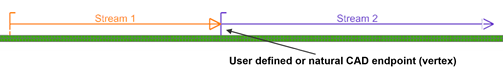
- Connecting thermal streams using auto-connect options
- When thermal streams share a user-defined or natural CAD endpoint or line,
you can use auto-connect options to automatically ensure.
- Mass flow continuity: The solver carries mass flow from upstream streams, replacing manual definitions such as DMO or MMIX.
- Inlet temperature continuity: The solver derives inlet temperature from upstream stream outlets, replacing STO or MIX functions.
- Flow reversal handling: The solver recalculates mass flow based on upstream or downstream values if flow reverses.
- Temperature reversal handling: The solver recalculates inlet temperature based on upstream or downstream values if flow reverses.
When a stream inlet or outlet has multiple geometrical and user-defined connections, the thermal solver merges all these connections into a single connection. Each connection provides one linear equation representing mass flow conservation at the connection.
The temperature at a connection depends on the temperature and mass flow of the fluid coming to the connection.
Where:
- is the enthalpy of the inlet stream.
- is the mass flow of the inlet stream.
- is the specific heat capacity.
- Connecting thermal streams using Junction
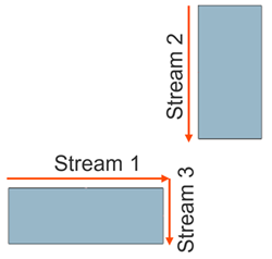
- When streams do not share a common endpoint or edge, you can use the
Junction command to manually connect streams that
are disconnected in the digital model but connected in the physical model.
This ensures mass flow continuity and heat balance.
This allows you to:
- Specify incoming and outgoing streams at a junction.
- Simplify the setup of stream connections.
- Automatically compute mass flow and thermal properties at the junction when used with Auto Connect options.
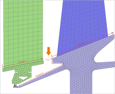
- Connecting thermal streams using Junction and auto-connect options
- In the following example, the auto-connect option is enabled for Stream 3,
establishing a connection with Stream 1. Additionally, Stream 3 is linked to
Stream 2 using the Junction command.
The thermal solver calculates the inlet temperature for the Stream 3 as:
Hands-on material
To gain experience with the topics discussed here, complete the following: