Defining thermal voids
This topic explains how to define and use Thermal Void to model enclosed fluid regions with simplified thermal behavior, including setup, governing energy equation, required properties, and options to represent heat transfer, capacitance, and interactions with surrounding solids and streams.
This lesson may include hands-on exercises. Review the Discussion section for background information or click the button to proceed to the practical section.
Discussion
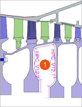
A thermal void (1) represents a fluid volume characterized by:
- A single uniform temperature.
- Instantaneous thermal equilibrium with negligible heat capacity.
- Surfaces inside the void convecting to the same fluid temperature computed during the solve.
A thermal void requires defined regions, each with its own pressure, HTC, and rotational effects. It is mainly used for:
- Turbine cavity fluid regions.
- Chambers where multiple surfaces exchange heat with a common fluid volume.
- Thermal void energy equation
To define a thermal void, you must specify heat load and capacitance in the energy equation for void:
Where:
- is the volume of the void cavity.
- is the density of the fluid material in the void cavity.
- is the specific heat of the fluid material in the void cavity.
- is the void fluid temperature, computed by the thermal solver.
- is the solid body temperature, computed by the thermal solver.
- is the solid-fluid interface area determined by the thermal solver.
- is the specified local heat transfer coefficient.
- is the specified heat load into the void in watts. If a stream feeds into a void, you can use the PWR standard function. If a void feeds another void, you can use the PWRV function.
You can specify the volume or the effective capacitance of the void. Also, you can enable the No Capacitance option to set the right-hand side of the energy equation to zero.
In the absence of heat load and capacitance, the void acts to average the temperatures of the surrounding metal.
- How are thermal voids modeled?
- A thermal void models enclosed or semi-enclosed fluid regions using
simplified thermal behavior while maintaining flexibility in how heat
transfer is defined. The heat flux at the void boundaries can vary both
spatially and over time. You can divide these boundaries into multiple
Void Regions to assign local properties such as
pressure, HTC, and other thermal characteristics.
You can optionally apply a total power input to the void. Depending on the modeling objective, you can represent the void with thermal capacitance to account for transient fluid energy storage, or treat it as massless, assuming instantaneous thermal equilibrium.
Thermal Void can exchange heat with connected Thermal Stream or with other voids, enabling the representation of complex thermal interactions.
A single Thermal Void load can reference up to 20 void regions defined by surface or edge selections. You can also apply area correction factors for internal edges with different thicknesses to improve modeling accuracy.
Hands-on material
To gain experience with the topics discussed here, complete the following: