Introducing coupled 1D duct fluid network
This topic explains how to model convection using a coupled 1D duct fluid network by linking 1D flow elements to thermal surfaces.
This lesson may include hands-on exercises. Review the Discussion section for background information or click the button to proceed to the practical section.
Discussion
Use a coupled 1D duct fluid network to model convection by connecting 1D flow elements to thermal surfaces.
| Boundary conditions | Type | Description | Output quantity | Representation |
|---|---|---|---|---|
| Temperature constraint (1) | Temperature | Defines source temperatures for the 1D fluid network. | Temperature | 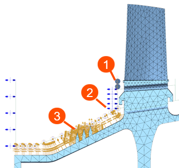 |
| Duct Flow Boundary Condition (2) | Duct Fan/Pump | Defines mass flow for duct elements. | Mass Flow | |
| Duct Label | References ID for other duct flows or streams. | N/A | ||
| Duct Total Pressure Duct Static Pressure |
Applies pressure to surfaces connected to the duct. | Pressure | ||
| Thermal Coupling - Convection (3) | Convection Coupling | Couples convective surfaces to the 1D fluid network. | Heat Transfer Coefficient | |
| Thermal Loads | Heat Generation | Defines heat generation, for example windage, in 1D elements or nodes. | Heat Generation |
- Setting up convective boundary conditions with Method 2
- The following example shows how to setup convective boundary conditions with
1D ducts:
- Blade cooling flow– Duct Flow Boundary Conditions + Convection Coupling
- Disk cavity purge flow– Duct Flow Boundary Conditions + Convection Coupling
- Vane cooling flow – Duct Flow Boundary Conditions + Convection Coupling
- Cavity flow — Duct Node Convective Coupling
- External environment — Convective Zone
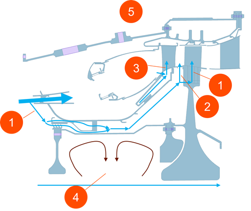
Assign each flow type to the appropriate convection boundary condition to represent the physical behavior accurately.
Hands-on material
To gain experience with the topics discussed here, complete the following: