Managing parts and assemblies
This topic explains how to manage parts and assemblies in WEM using associative geometry, collaborative simulation capability, and integration of submodels into a full engine simulation.
This lesson may include hands-on exercises. Review the Discussion section for background information or click the button to proceed to the practical section.
Discussion
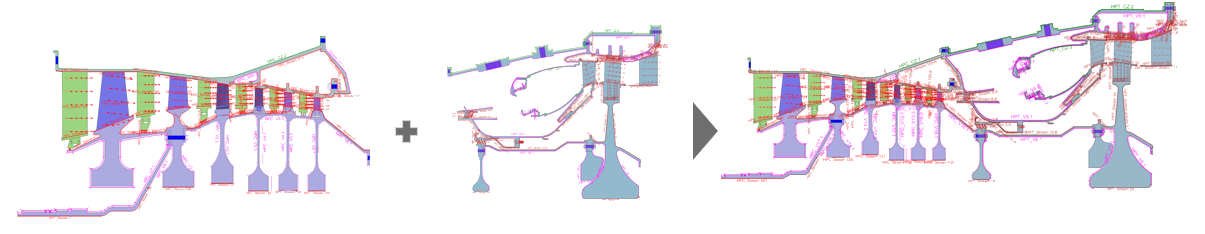
Whole Engine Models are typically developed using a modular workflow where individual engine sections are created, validated, and later integrated into a complete engine simulation.
To handle large and complex models, engineers typically divide the engine into sections, for example, compressor and turbine modules. Each section is modeled and validated independently before being assembled into the full engine model. This modular approach improves robustness and simplifies debugging.
- Associative geometry workflow
- You can extract the geometry of each subassembly directly from the complete
3D CAD model while maintaining full associativity with the global
design.
When the design geometry changes, the software automatically updates the associated analysis model: , , and no major rework is required.
- The mesh regenerates.
- Boundary conditions remain attached to the geometry.
- Minimal manual rework is required.
- Assembly FEM workflow
- Use an assembly FEM files to create CAE models that consist of multiple FEM
files.
An assembly FEM file contains:
- Occurrence and position data for component FEMs.
- Connection elements that join component FEMs into a system.
- Material and physical-property overrides on component FEM meshes.
- Collaborative simulation workflow
- Associative linking between Simulation files enables automatic and
consistent sharing of simulation data across models.
Use Simulation Interface to connect different simulation models by linking key elements such as solver settings, root folders, and boundary conditions. When these elements are shared, all dependent data—such as fields, expressions, regions, selections, and groups—is automatically included. Any changes made in the source simulation propagate directly to the linked models.
- Typical integration workflow
- A typical integration workflow includes:
- Build and solve each engine section separately.
- Create and validate models for each major module, such as the compressor module, turbine module, and bearing support structure.
- Ensure each section runs correctly.
- Assemble component meshes into an AFEM.
- Import meshes from each independent analysis.
- Ensure consistent coordinate systems and mesh connectivity where required.
- Create a Simulation file.
- Build a global SIM referencing the assembled AFEM.
- Import linked boundary conditions.
- Bring in boundary conditions from individual analyses using Import Simulation Entities or Simulation Interface, including simulation objects, loads, and constraints.
- Build and solve each engine section separately.
Hands-on material
To gain experience with the topics discussed here, complete the following: