Gas turbine design disciplines and data exchange
This topic introduces the main engineering disciplines involved in gas turbine design and explains how they exchange data throughout the development process. You will learn how different teams collaborate, what data they produce, and how iterative workflows drive the final engine design.
Discussion
Gas turbine design requires collaboration across multiple specialized engineering disciplines. Each team uses dedicated simulation tools to model specific physical phenomena and contribute to the overall engine performance.
Engineers continuously exchange information between disciplines until the design converges. The main design targets include cost, efficiency, and power output.
Design cycles can take several years to complete. Engineers must therefore minimize the number of iterations and ensure accurate data transfer between tools.
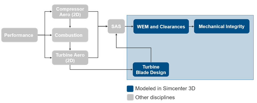
- Design disciplines overview
- Gas turbine development involves several key disciplines, each responsible
for a specific aspect of the engine:
- Performance (1), which defines high-level operating conditions and overall engine behavior.
- Compressor Aero 2D (2), which calculates primary flow-path conditions.
- Secondary Air System (SAS) (3), which designs and analyzes the cooling network.
- WEM and Clearances (4), which calculate transient thermal behavior of the engine and predicts clearances.
- Mechanical Integrity (5), which determines how many start-up cycles the rotor disk can withstand.
- Turbine Blade Design (6), which calculates required cooling flow for blades.
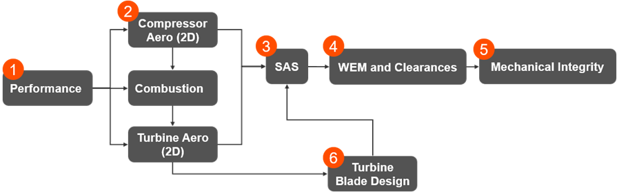
All these disciplines interact and influence each other throughout the design process.
- Performance data
- The performance discipline defines the main operating parameters of the
engine at key locations. In the following image, these locations are marked
by orange points and vertical dashed lines, which represent standard engine
stations used in performance analysis.
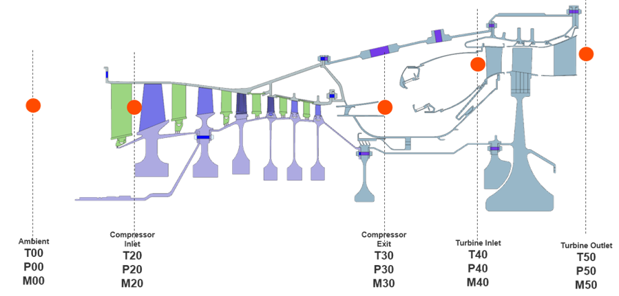
Typical outputs include:
- Temperature, pressure, and Mach number at key stations such as the inlet, compressor exit, turbine inlet, and turbine outlet.
- Compressor shaft power and torque.
- Turbine shaft power and torque.
- Compressor and turbine 2D Aero output data
- The compressor and turbine aerodynamics teams calculate flow conditions
along the primary flow path. In the following image, the orange points
distributed along this path represent discrete calculation locations used by
2D aerodynamic models.
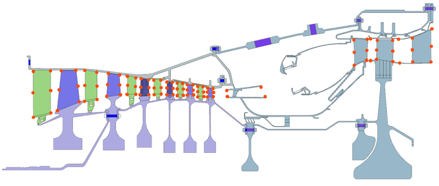
Typical outputs include:
- Temperature and pressure distributions.
- Swirl ratio and flow angles.
- Flow conditions at multiple locations along the flow path.
These teams must account for interactions with the secondary air system by iterating on flow exchanges.
- Secondary Air System (SAS)
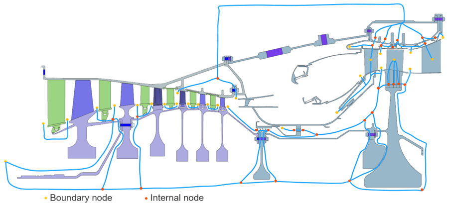
- The SAS discipline models the internal cooling flow network within the
engine. In the following image, the SAS network appears as a system of blue
flow paths routed through internal cavities, discs, and blade passages.
These paths show how air is extracted from the compressor and redistributed
throughout the engine to perform cooling and sealing functions. The nodes
along these paths represent the SAS computational model.
Typical outputs include:
- Pressure and mass flow rates.
- Flow distribution through internal passages.
- Windage heating effects.
SAS models are typically adiabatic but include the effects of rotor work on the fluid.
- WEM and clearances
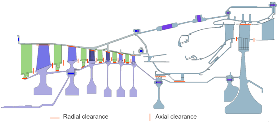
- The WEM discipline evaluates the thermal behavior of the engine and predicts
component clearances. In the following image, clearances are highlighted
throughout the engine:
- Radial clearances appear between rotating blades and stationary casings along the compressor and turbine.
- Axial clearances appear between adjacent components such as discs, seals, and structural parts.
Typical outputs include:
- Radial and axial clearances.
- Metal temperatures.
- Thermal growth and deformation.
These results support mechanical integrity assessments, rub-risk evaluation, and lifetime prediction.
Engineers often reconstruct part-load and transient conditions because mission data is usually available only at full load.
- Mechanical integrity
- The mechanical integrity discipline evaluates the structural durability of
engine components by analyzing:
- Fatigue life.
- Creep behavior.
- Number of allowable start-up cycles.
- Risk of structural degradation.
These analyses ensure safe and reliable engine operation over its lifetime.
- Turbine blade design
- The turbine blade design team determines the cooling requirements for blades operating in extreme temperatures. They use inputs from aerodynamics, performance, and SAS to calculate the required cooling flow and ensure acceptable material temperatures.
- Simcenter 3D for engine design
- Simcenter 3D provides an integrated environment for engine design by connecting WEM
and clearances, mechanical integrity, turbine blade , and structural
analysis.