Introducing surface-based convection boundary conditions
This topic explains how to model surface-based convection using Thermal Streams, Thermal Voids, and Thermal Convective Zones, and how to apply them to represent different flow behaviors and heat transfer mechanisms.
This lesson may include hands-on exercises. Review the Discussion section for background information or click the button to proceed to the practical section.
Discussion
Use surface-based convection boundary conditions to model fluid–solid heat exchange directly on walls. This approach the uses Thermal Streams, Thermal Voids, and Thermal Convective Zones loads.
| Boundary conditions | Description | Output quantity | Representation |
|---|---|---|---|
| Thermal Stream (1) | Combine mass flow with convective coupling. Define inlet temperature, heat load (Q), and pressure. | Mass flow, fluid temperature, heat transfer coefficient (HTC), heat load (Q), pressure | 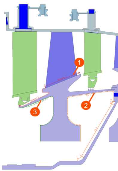 |
| Thermal Void (2) | Represent a stagnant cavity with HTC and no fluid connection. | HTC and pressure | |
| Thermal Convecting Zone (3) | Model a solid surface in contact with a fluid at a specified temperature and infinite heat capacity. | Temperature, HTC, and pressure |
- Setting up convective boundary conditions with Method 1
- In a WEM, model the flow network using different convective boundary
conditions.
For example, in the highlighted region, you can identify several types of flow:
- Main compressor flow — Thermal Streams
- Cooling flow — Thermal Streams
- Mixing flow — Thermal Voids
- Cavity flow — Thermal Voids
- Leakage flow — Thermal Streams
- External environment — Thermal Convective Zone
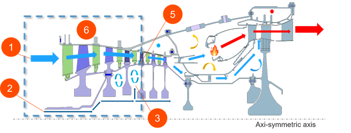
Assign each flow type to the appropriate convection boundary condition to represent the physical behavior accurately.
Hands-on material
To gain experience with the topics discussed here, complete the following: