Comparing two methods
This topic compares thermal streams and 1D duct networks, as well as voids and duct-node approaches, highlighting their differences in workflow, control, and suitability for modeling convective heat transfer in turbomachinery.
This lesson may include hands-on exercises. Review the Discussion section for background information or click the button to proceed to the practical section.
Discussion
Both thermal streams and 1D duct networks are used to model convection between a fluid and solid surfaces, but they differ in workflow, flexibility, and level of control. Similarly, the void and duct-node approaches provide two methods for modeling convection in cavities.
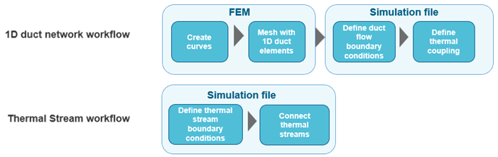
- Comparing thermal streams and ducts
- Thermal streams provide a simpler workflow, in which the solver
automatically generates the underlying fluid representation. In contrast,
the 1D duct approach requires users to explicitly create and define the duct
network, offering greater control and traceability.
Thermal stream approach
- Is defined entirely within the simulation file.
- Requires fewer boundary conditions.
- Automatically handles fluid behavior and flow paths.
- Allows definition of endpoints without splitting geometry.
- Applies windage and heat transfer coefficient (HTC) correlations directly.
1D duct approach
- Requires creation of curves and meshing with 1D elements.
- Requires explicit definition of boundary conditions such as mass flow, pressure, and temperature.
- Uses convection coupling to link ducts to solid surfaces.
- Enables direct comparison with external 1D system models.
- Comparing void and duct-node approaches
- The void approach represents a cavity as a single fluid region with uniform
temperature, while the duct-node approach uses discrete nodes to capture
spatial variations and interactions.
Void approach
- Represents the cavity as a single fluid region with uniform temperature.
- Computes fluid temperature based on surrounding regions and HTCs.
- Defines convective surfaces at the region level.
- Allows each region to have its own HTC, total temperature effects, and pressure.
- Creates a 0D element representing the cavity fluid, acting as a single temperature sink.
- Supports heat loads to introduce energy from other sources or streams.
Duct node approach
- Represents convection using discrete fluid nodes connected to surfaces.
- Uses Duct-Node Convection Coupling to model heat transfer between 1D duct nodes and solid surfaces.
- Allows multiple nodes to represent spatial variation in the fluid.
- Applies a single HTC definition to all surfaces within a coupling, which can vary spatially or be user-defined.
- Supports total temperature effects for more accurate convection modeling.
If only one node is used, the behavior is similar to the void approach.
Hands-on material
To gain experience with the topics discussed here, complete the following: