Meshing strategy
This topic explains how to create finite element models for WEM by combining multiple mesh types and abstraction levels.
This lesson may include hands-on exercises. Review the Discussion section for background information or click the button to proceed to the practical section.
Discussion
WEM meshing focuses on achieving a balance between accuracy and efficiency:
- Capture axisymmetric physics with the minimum number of degrees of freedom.
- Resolve critical regions such as clearances, interfaces, and thermal gradients.
- Keep models robust and update-friendly for design iterations.
Use the following main meshing strategies:
- 3D solid elements to model detailed sectors of the engine such as rotor or stator stages when local 3D effects are important.
- 2D axisymmetric elements to represent disks, shafts, and casings by modeling a cross-section and revolving it around the axis. This approach forms the backbone of WEM because of its efficiency.
- 2D plane stress, plane strain, and chocking elements to model 2D representations of blades, vanes, and shrouding.
- 1D elements to model internal flow networks, for example, cooling, leakage and structural connections between components.
- 0D elements to represent lumped properties such as mass or inertia for components not explicitly modeled.
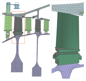
- 3D meshing
- Use 3D Tetrahedral Mesh to represent a sector of the
axisymmetric model, such as a rotor or stator stage, when a more detailed 3D
representation is necessary.
- 2D meshing
- Use 2D Mesh to:
- Perform axisymmetric analysis on bodies of revolution by creating the FE model on a section plane on one side of the rotational axis. This greatly reduces solution time.
- Build hybrid models that combine axisymmetric, plane stress, plane strain, and other non-axisymmetric elements.
To ensure accurate results, correctly define the modeling 2D environment:
- Specify the modeling plane and axis of rotation:
- ZX plane → Z-axis of rotation
- XY plane → X-axis of rotation
- Set the global cyclic analysis coordinate system as the default for boundary conditions.
- Align the center of rotation and the radial axis of the axisymmetric model with the absolute coordinate system.
- Ensure geometry lies on the positive side of the plane (+X for XZ, +Y for XY).
- Use Reposition Master or similar commands if realignment is required.
- Axisymmetric and non-axisymmetric modeling
-
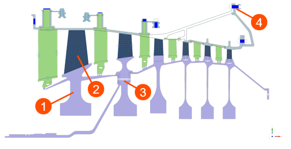
Axisymmetric 2D solid elements (1):
- Are geometrically and thermally axisymmetric with respect to the axis of revolution.
- Do not include tangential (circumferential) thermal gradients.
- Represent a fully revolved 3D shape for conduction and thermal capacitance.
- Are typically used for disks, shafts, and casings.
Non-axisymmetric features such as blades (2), holes (3), or bolts (4):
- Require projection of the 3D geometry onto the 2D axisymmetric plane.
- Represent features as 2D faces.
- Use plane stress elements to capture non-axisymmetric behavior.
- Require definition of element thickness and number of instances in Mesh Associated Data.
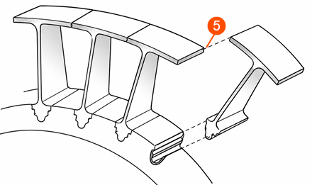
Chocking elements (5):
- Represent repeating gaps and leakage paths such as labyrinth seals and purge cavities.
- Capture periodic non-axisymmetric effects in an axisymmetric model.
- Model components with gaps that open and close during operation.
- Carry compressive hoop stress when the gap is closed and no hoop stress when the gap is open, allowing realistic representation of non-continuous rings.
Chocking elements are typically used for components such as labyrinth seal rings, segmented stator shrouds, seal carriers, or backing rings, and sometimes retaining or snap rings. These designs intentionally include gaps to accommodate thermal expansion, reducing mechanical stresses by allowing controlled contact as the engine heats up.
Chocking elements behave differently depending on the analysis type:
- In thermal analysis, they act like plane stress elements, enabling accurate heat transfer and radiation modeling across gaps.
- In structural analysis, they behave like axisymmetric elements under compression but cannot carry tensile hoop stress.
- What matters for 2D meshing and property definition?
- To obtain accurate thermal and structural behavior in a 2D WEM model, you
must carefully define how the mesh, thickness, and properties represent the
original 3D system.
You must define:
- Number of instances to determine the total convective area, conduction paths, and mass representation.
- Edge area control, such as Add or Subtract, to specify which edges
contribute to surface area calculations.
- Some edges should contribute to convective area such as external surfaces.
- Others should not such as internal edges and intersections.
- Local thickness to provide the physical thickness that a 2D model
does not inherently have.
- Directly affects thermal mass, structural stiffness, and heat flow paths.
- Mass check to ensure that the 2D model accurately represents the original 3D geometry.
- 2D Thickness Definition
- Define the 2D thickness by converting the original 3D geometry into an
equivalent 2D representation that preserves the correct mass and physical
behavior of the component.
The recommended approach is to subdivide the 3D geometry into regions that correspond to the intended 2D mesh topology, then calculate the equivalent thickness for each region from the ratio of 3D volume to 2D area:
Where:
- is the equivalent 2D thickness.
- is the volume of the corresponding 3D region.
- is the area of the associated 2D region.
For plane stress models, the calculated thickness may additionally be scaled to account for repeated sectors or multiple instances represented by the 2D model.
This approach ensures that the 2D model preserves the correct volume and physical behavior of the 3D component.
After defining thickness, use the Solid Properties command on the 2D mesh to verify that the computed volume matches the original 3D volume.
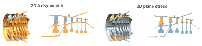
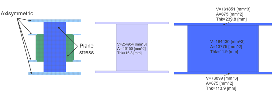
The following image illustrates how thickness varies depending on the modeling approach:
- Axisymmetric elements represent fully revolved geometry. The thickness reflects the entire circumferential volume.
- Plane stress elements represent localized non-axisymmetric region, requiring adjusted thickness to account for repeated instances.
- Defining thickness using a field
- When there is no predefined thickness source and the solver cannot derive it
from the geometry, you must define the thickness with an expression.
- Right-click the mesh node and choose Edit Mesh Associated Data.
- From the Thickness Source list, select Field/Expression.
- In the Thickness box, enter the expression.
For example: 0.024*2*pi()*radius to define the thickness.
Make sure to define all variables in the Expressions dialog box.
- Verifying element thicknesses
- You can use:
- Plot Thickness Contours to generate a contour plot of shell-element thicknesses as a standard post view.
- Thickness Information to create a color-coded line display that shows the general statistical distribution of the thickness values across your 2D mesh.
You can use the thickness display to quickly identify:
- Sudden changes in color that may indicate incorrectly assigned thickness values.
- Elements that do not have an assigned thickness.
- 2D dependent mesh
- For cyclic symmetry, the radial, tangential, and axial displacements
relative to the axis of rotation are identical at equivalent positions on
the repeated faces.
To model cyclic symmetry accurately:
- Create a 2D Dependent Mesh on the repeated faces to ensure nodes are placed at equivalent positions.
- Use the 2D dependent mesh to seed a 3D mesh of the body.
- 1D meshing
- Create duct networks by meshing curves or edges that represent the duct
centerline using the 1D Duct type elements. The free
ends of the duct network model known flow boundary conditions or openings to
a fluid environment.
To ensure that all duct elements point in the same direction, select Auto Chain Selection. The software uses the direction of the first edge or curve you select to set the direction of the other edges or curves.
To ensure that no duplicate nodes exist where two curves join, select Merge Node.
- 0D meshing
- Use 0D Mesh with Concentrated
Mass element types to model components that are not
explicitly meshed.
0D elements:
- Can be created on nodes or geometry, usually points.
- Are often connected to the adjacent mesh using 1D connections.
- Use Mesh Associated Data to define the component mass.
Hands-on material
To gain experience with the topics discussed here, complete the following: