Fundamentals of turbomachinery systems
This topic introduces turbomachinery and explains how gas turbines convert working-fluid energy into mechanical energy or thrust. You will learn how turbomachines are classified, how the Brayton cycle describes gas turbine operation, and how the main gas turbine sections, components, and cooling systems support safe and efficient performance.
Discussion
- Power-producing turbomachines, such as steam turbines, gas turbines, hydraulic turbines, aeroengines, and wind turbines.
- Power-absorbing turbomachines, such as compressors, pumps, and fans.
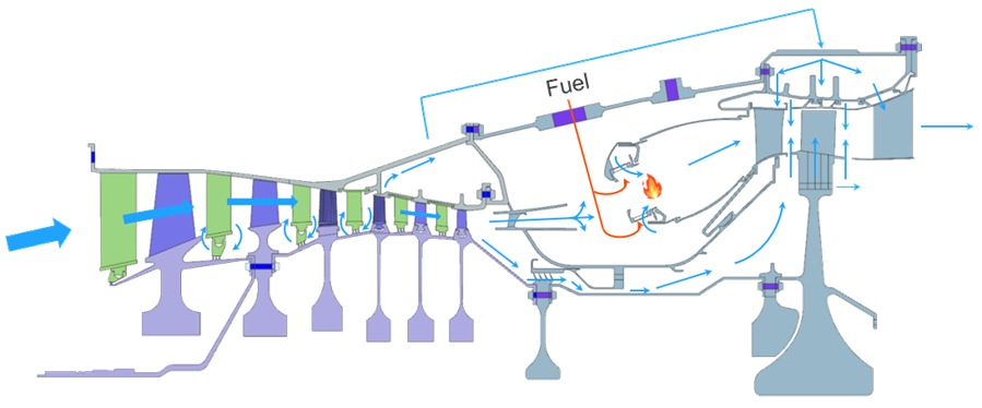
- What is a gas turbine?
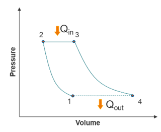
- A gas turbine is a machine used to generate mechanical energy or thrust. It
operates based on the open Brayton cycle, where air is compressed (1-2),
heated (2-3), expanded, (3-4) and exhausted (4-1) as shown in the
image.
The gas turbine process consists of the following steps:
- Compression: The compressor draws air from the ambient atmosphere and increases its pressure and temperature.
- Combustion (heat addition): The combustor mixes the compressed air with fuel and ignites the mixture, significantly increasing the energy of the flow.
- Expansion: The high-energy gases expand through the turbine, generating mechanical energy that drives the compressor and produces useful work.
- Exhaust: The system discharges the gases into the atmosphere in an open-cycle configuration.
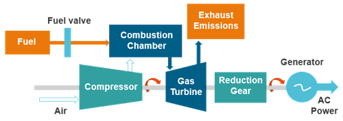
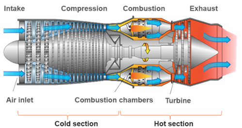
- Gas turbine sections
- The gas turbine consists of two main sections: the cold section and the hot
section. It includes three primary components: the compressor, combustion
chamber, and turbine.
The compressor increases the air pressure before delivering the air to the combustor. The combustor then mixes this compressed air with fuel and ignites it, significantly increasing the energy of the flow. As the hot gases expand through the turbine, they cool and are eventually discharged through the exhaust.
Airplane Flying Handbook, U.S. Department of Transportation, Federal Aviation Administration, 2004.
Typical temperature ranges in a gas turbine include:
- Compressor outlet: ~300–500 °C
- Combustion flame: ~1800–2000 °C
- Turbine inlet: ~1400–1700 °C
- Exhaust: ~450–700 °C
Heat transfer, aerodynamics, and structural behavior interact strongly within the engine. Engineers must consider all these physical phenomena together to fully understand gas turbine performance. The heat transferred to the metal components significantly affects their deformation and stress levels, making thermal management a critical aspect of gas turbine design.
- Gas turbine cooling and internal air system
- Cooling is critical in gas turbines to prevent material creep, oxidation,
and melting of components. Although turbine inlet temperatures can reach
around 1500 °C, component materials are typically limited to about 700 °C.
Advanced cooling techniques are therefore required to maintain structural
integrity and extend component life.
The following image illustrates a typical internal air system within a gas turbine. Compressor bleed air flows through a network of internal passages and cavities to cool critical components such as turbine blades, vanes, and discs.