How to model multiple passages with a single thermal stream
This example shows how to model multiple holes with a single cylindrical stream.
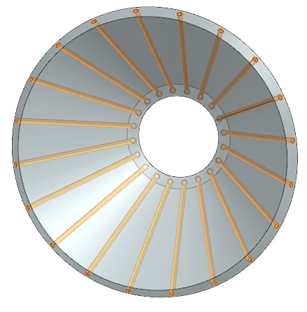
This modeling approach is effective when multiple holes are circumferentially distributed in a circular pattern around the axis of rotation, and oriented in the same cylindrical direction. In this case, you can represent the flow through all of the holes using a single cylindrical thermal stream.
Using one stream for multiple holes instead of one stream per hole removes the limit of 10 streams that can be mixed using the MIX and MMIX thermal-flow functions.
Details
To model multiple holes using a single cylindrical stream, use the following guidelines:
- Create a thermal stream of type One-Sided Stream on Faces (Cylindrical Components).
- Select the set of holes that are all circumferentially distributed in a circular
pattern around the axis of rotation.
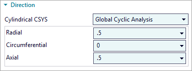
- Set the radial, circumferential, and axial components of the stream flow
direction with respect to the selected cylindrical CSYS. This means that the
global cyclic axis of your model is used as the cylindrical axis, typically the
engine centerline. You specify the direction of the thermal stream using three
components as shown in the following image.
- Specify thermal stream conditions such as the mass flow, initial temperature,
and absolute pressure. If the holes are identical and evenly spaced, the solver
distributes the flow across the entire cylindrical duct.Note:
You must specify the total mass flow for the entire circumferential region, not just the flow through a single hole.
- Specify the heat transfer coefficient (HTC) applied to the entire annular flow
path. A cylindrical thermal stream models one continuous 1D flow domain, an
annular duct, wrapping around the geometry. The thermal solver couples this duct
to the selected circumferential surface area.
-
HTC is applied to the total wetted area.
-
HTC governs heat transfer between the annular duct and all surfaces along that duct.
-
HTC is not subdivided by geometric features such as holes, slots, or ports.
-
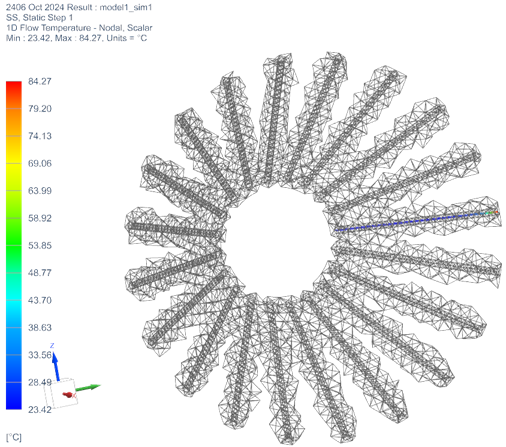
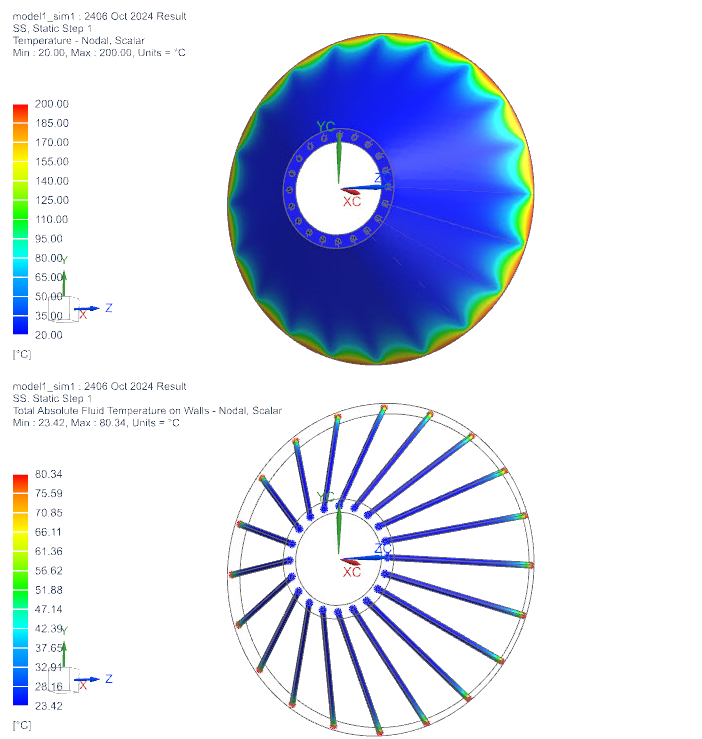
- After solving, always review the solver-created duct geometry, the temperature
distribution, and the thermal coupling to the solid to ensure that they meet
your expectations and accurately represent the intended flow behavior.
- In post-processing, under the Groups
node→Thermal Stream - Nodal, display thermal stream
groups to graphically identify whether the created ducts and solid elements are
correctly connected thermally.