Relative temperature effects
This topic explains how to account for total temperature effects in turbomachinery simulations, particularly in systems with rotating and stationary components.
This lesson may include hands-on exercises. Review the Discussion section for background information or click the button to proceed to the practical section.
Discussion
In a system with rotating and stationary parts, the fluid temperature seen by a rotating surface differs from that seen by a stationary surface. To account for total temperature effects, you need to consider both the static and dynamic components:
Total Specific Enthalpy = Static Specific Enthalpy + Kinetic Energy
- is the static temperature.
- is the flow velocity.The definition depends on the reference frame:
- Absolute:
- Relative: , where ω is the rotation speed of the engine domain.
Several fluid temperature definitions are used in convection calculations:
- Static temperature, Ts is the temperature of a fluid that is not in motion. It is used to evaluate bulk fluid properties. Use the GetFluidTemperatureOfType plugin function to request solver temperature output if necessary.
- Total Absolute Temperature, Tt, abs, is the inlet fluid total temperature relative to a stationary component.
- Total Relative Temperature, Tt, rel, is the inlet fluid total temperature relative to a rotating component.
- Neglect Wall Rotation is used when the surrounding components are stationary or rotate slowly.
- Correct for Wall Rotation is used when the components that surround the fluid are rotating.
- Relative Temperature Reference Frame is used when the analysis is performed entirely in a rotating reference frame.
- Modeling total temperature with Neglect Wall Rotation
- The thermal solver calculates the total absolute fluid temperature,
Tt, abs, as:
Where:
- is the static temperature, the temperature of a fluid that is not in motion.
- is the specific heat of the stream fluid material.
- is the fluid swirl velocity.
- is the fluid axial velocity.
The following example illustrates rotating fluid system showing swirl velocity, axial velocity, and wall velocity relative to a stator and rotating fluid flow.
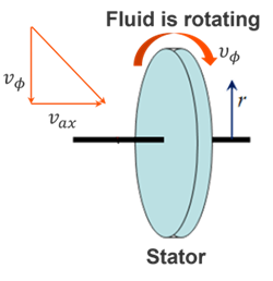
In this case:- The inlet temperature is interpreted as Tt, abs
- The fluid velocity is equal to 0, so Ts= Tt, abs.
- Modeling total temperature effects on the wall due to rotating flow
- The thermal solver computes the total relative fluid temperature,
Tt, rel, seen by the rotating components, which is
determined from the total enthalpy:
Where:
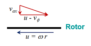
- is the fluid swirl velocity.
- is the fluid axial velocity, which is assumed to be 0.
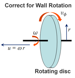
- is the wall velocity, where ω is the rotor rotational rate and r is the radius.
The following example illustrates wall-rotation correction for a rotating disc, showing wall velocity, fluid swirl velocity, and angular rotation about the shaft axis.
The relationship between total temperatures is:
The thermal solver assumes the inlet fluid temperature is defined as Tt, abs.
- Modeling total temperature effects on wall due to rotating flow
- The thermal solve computes the total relative fluid temperature, Tt,
rel, using:
The total absolute fluid temperature is then recovered from the total relative fluid temperature as:
The thermal solver assumes the inlet fluid temperature is defined as Tt, rel.
The thermal solver solves the heat transfer equations as a function of duct relative temperature, wall rotational speed, and swirl velocity in the specified relative reference frame.
The following example shows the relative reference frame (orange) between rotating and stationary parts.
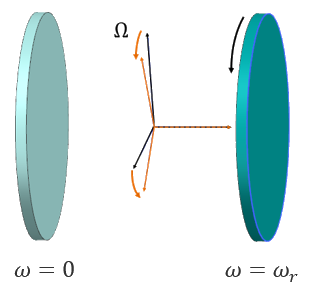
You can define the angular velocity of this reference frame using the Relative Reference Frame type of the Rotation load. If you do not define the relative reference frame angular velocity, the thermal solver uses the maximum rotor rotational speed as the reference-frame angular velocity.
All 1D duct and stream elements in the 1D duct network reference the same relative reference frame for total temperatures when you set the Rotational Effects to Relative Temperature Reference Frame in defined thermal streams, and ducts coupling to the walls.
- How to choose the relative temperature effects option
-
Scenario BC temperature frame (what you specify) Computed fluid temperature frame (what solver computes) Results available in post-processing Option to choose No rotating wall effects are needed Total absolute fluid temperature Total absolute fluid temperature Total absolute fluid temperature Neglect Wall Rotation Wall is rotating; swirl or rotation must be accounted for Total absolute fluid temperature Total absolute and total relative fluid temperatures Total absolute and total relative fluid temperatures Correct for Wall Rotation User defines temperature in the rotating frame Total relative fluid temperature Total relative fluid temperature Total relative and total absolute (converted) fluid temperatures Relative Temperature Reference Frame - Accounting for rothalpy
- When computing the total temperature effects in a relative reference frame,
enable the Automatically Calculate Rothalpy option to
conserve rothalpy, , the
rotational stagnation enthalpy. When enabled, the thermal solver
automatically accounts for windage and pumping due to rotation by adding the
appropriate heat fluxes when computing the fluid total relative temperature.
Under adiabatic conditions, rothalpy is conserved along the
radius:
Where:
- is the angular velocity of the reference frame.
- is the fluid radius.
If this option is disabled, the following rotational kinetic energy term is not included:
Note:Enable this option only if rotational heat effects are not already included through heat loads or boundary conditions; otherwise, disable it to avoid double counting.
- Specifying swirl velocity
- For all three total temperature effect methods, you can specify the swirl
velocity or the swirl ratio. When you specify the swirl ratio, the solver
computes the swirl velocity as:
Where:
- is the fluid swirl velocity.
- is the wall velocity.
- is the rotor rotational rate.
- is the radius.
- is the fluid
swirl ratio, which is computed as:
Hands-on material
To gain experience with the topics discussed here, complete the following: