Introducing Whole Engine Model (WEM)
This topic introduces the WEM and explains its role in gas turbine design. You will learn how WEM captures the thermal and structural behavior of the engine, what inputs it requires, and how it supports clearance and mechanical integrity assessments.
Discussion
The WEM is a thermal-structural transient analysis of a gas turbine. It captures how the engine responds over time during operating conditions such as startup, shutdown, and load changes.
The model uses a combination of axisymmetric, plane stress, and 3D elements to represent engine components while maintaining computational efficiency.
WEM relies on Secondary Air System (SAS) data and focuses primarily on heat transfer. This thermal behavior drives metal temperatures, thermal expansion, and structural response.
WEM plays a critical role in evaluating rotor and casing integrity by predicting clearances between rotating and stationary components. These clearances directly affect engine efficiency, reliability, and the risk of component contact.
- What are the challenges?
- The following are the primary challenges for WEM in terms of time and
effort:
- Assembling and applying data from multiple sources into one model.
- Updating geometry and boundary conditions to account for design changes or to optimize clearances.
- Running and extracting data across multiple transient cycles.
- Ensuring the accuracy of heat transfer assumptions despite correlation limitations.
- WEM input data
- To perform a transient WEM analysis, you must define a complete condition
sequence representing the engine’s operating history.
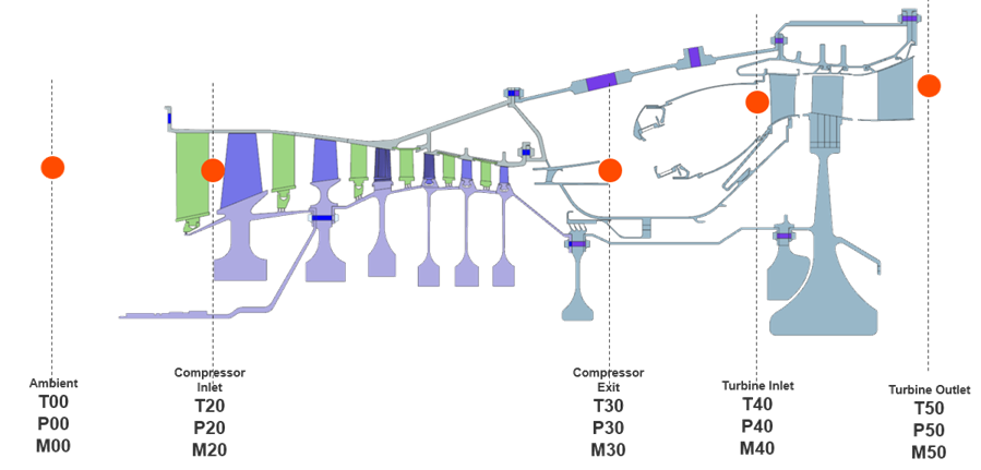
Typical inputs include:
- Time-dependent operating conditions.
- Temperatures and pressures at key stations.
- Mass flow rates and heat transfer coefficients from internal flows.
- Shaft speeds and mechanical loading schedules.
A key challenge is that performance data is often available only at the design point (100% load). You must therefore construct or scale off-design conditions.
- Off-design conditions
- You must account for various off-design scenarios, including:
- Startup and shutdown.
- Partial-load operation, for example ~70% load.
- Extreme ambient conditions.
- Engine restarts.
- Different startup profiles, for example simple cycle vs. combined cycle.
These conditions often generate the most critical thermal and mechanical loads, which directly influence:
- Clearance design
- Thermal stress predictions
- Component life assessment
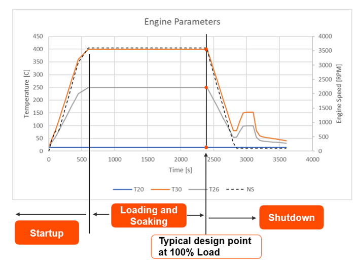
- How to account for startup and shutdown?
- Start by scaling the main engine parameters, such as temperature (T30),
pressure (P30), and mass flow rate (M30).
You can use different approaches depending on the available data and required accuracy. Common approaches include:
- Scaling existing measurement data.
- Applying dimensionless scaling methods, such as Biot and Fourier numbers.
- Using physics-based models to connect all parameters consistently.
Then, scale the applied temperature, pressure, and flow based on these engine parameters.
For example, temperature scaling can follow a normalized relationship:
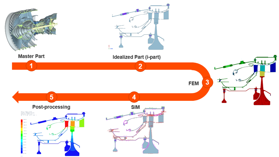
- WEM modeling workflow in Simcenter 3D
- The WEM modeling process in Simcenter 3D follows an associative workflow:
- Create or import the master part (CAD geometry).
- Generate an idealized part by defeaturing the geometry.
- Create the FEM file.
- Define boundary conditions and transient cycles in the Simulation file.
- Perform post-processing to evaluate results.
All models remain associative, so updates to the geometry automatically propagate through the idealized model, FEM, and simulation setup.