VVF8 - Low-speed turbulent, buice asymmetric diffuser
| Mesh | Test case |
|---|---|
| Coarse | SVTEST170 |
| Medium | SVTEST171 |
| Fine | SVTEST172 |
Description
This validation case examines the separated flow through a 2D asymmetric diffuser. This study is conducted in order to investigate the ability of the solver to predict the correct separation behavior with smooth walls and adverse pressure gradients. This flow has been experimentally studied by Buice and Eaton’s [35] research group. In this study, numerical results are compared with experimental data in the form of axial velocity plots and skin friction coefficients.
The following figure presents the geometry details. This geometry is taken from the NPARC [33] validation archive.
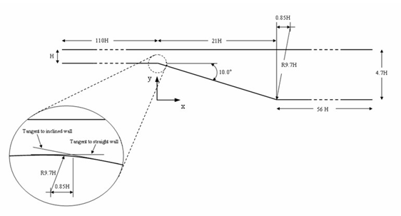
The height H of the inflow domain is 15.01 mm. The x-axis and y-axis are taken in the streamwise and straight-wall normal directions, respectively. The origin of the x-axis is located at the intersection of the tangents to the straight and inclined walls. The y-axis originates from the bottom wall of the downstream channel. The inflow region is 110H long. The lower wall of the diffuser section is at y = 0, and the outflow section is 4.7H high and extends 56H downstream (of the ramp). The geometry is partitioned in order to give three different sections: the inflow domain (length: 110H), the ramp domain (length: 21H) and the downstream domain (length: 56H).
Simulation model
This model uses Advanced Flow solution type.
A grid sensibility study uses three different mesh sizes in order to ensure a grid-independent solution. The swept mesh is made of hexahedral elements. The following mesh controls are used on the inflow domain:
- Height: 236 elements, bias origin at center of edge, 1.04 bias
- Width: 2 elements
- Length: 200 elements, bias origin at center of edge, 1.035 bias The following mesh controls were used on the ramp domain:
- Height: 236 elements, bias origin at center of edge, 1.04 bias
- Width: 2 elements
- Length: 141 elements, 1.01 bias
The following mesh controls are used on the outflow domain:
- Height: 236 elements, bias origin at center of edge, 1.04 bias
- Width: 2 elements
- Length: 100 elements, 1.014 bias
The fluid is modeled using air with the following properties:
- Mass density: ρ = 1.207 kg/m3
- Thermal conductivity: k = 0.0263 W/m·C
- Dynamic viscosity: µ = 1.85e-005 Pa·s
- Specific heat at constant pressure: Cp = 1007 J/kg·K
- Gas constant: R = 287 J/kg·K
The following boundary conditions are used:
- Flow Boundary Condition: Inlet Flow on the front of the inflow domain with a velocity of 19.812 m/s
- Flow Boundary Condition: Opening on the back of the downstream section
- Flow Surface: Boundary Flow Surface on the bottom and top surfaces using No Slip Wall with smooth wall friction
- Symmetry Plane on the right and left surfaces
The following solver options and parameters are set:
- Turbulence model: Shear Stress Transport-SST
- Initial conditions: Lengthwise velocity of 19.812 m/s with the intensity of 0.04 and eddy length of 0 mm set in the Turbulence Characteristics modeling object.
- 3D Flow Solver: Physical steady-state with time step = 0.001 s
- 3D Flow Solver: RMS Residuals = 1e-6
Theory
The low-speed turbulent flow through a 2D asymmetric diffuser has been studied extensively, both experimentally and numerically, in the literature [33], [35].
Results
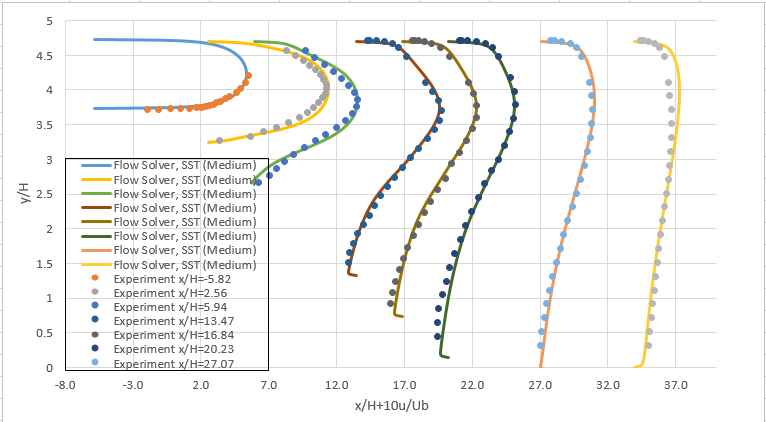
The following figure presents the velocity profiles at eight axial locations on the diffuser ramp.
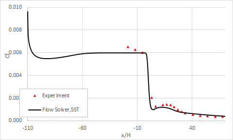
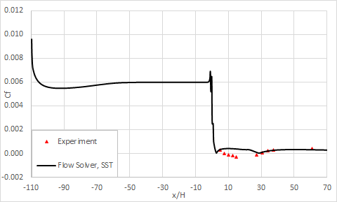
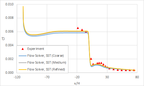
The following figures compare the evolution of the skin friction coefficient along the bottom and top surfaces. All of the profiles are normalized by the inlet flow velocity (Ub = 19.812 m/s). These results are plotted for the medium mesh size.
Upper wall skin friction coefficient:
Lower wall skin friction coefficient:
The skin friction coefficient Cf is computed using the following definition:
where τw is the wall shear stress and ρ is the inlet density of air.
The reattachment point measured experimentally is x/H = 29.23, while software predicts a reattachment point at x/H = 28.71 with SST, where x is the lengthwise coordinate and H is the inflow height.
The following figure presents a closeup of velocity profiles at several locations in the diffuser for different mesh sizes.
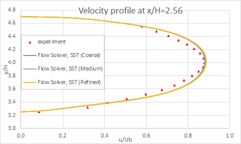
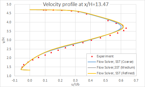
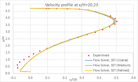
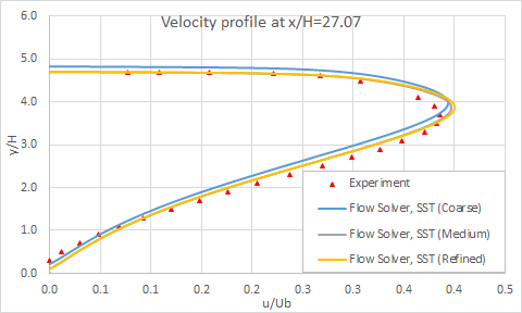
The following figure shows the grid sensibility on the skin friction coefficient.
The following table summarizes the number of nodes that are used for each mesh.
| Parameter | Coarse | Medium | Refined |
|---|---|---|---|
| Number of nodes | 157 794 | 314 262 | 628 524 |
