VVF2 - Incompressible laminar linearly decelerating flow (Howarth flow)
| Test case |
|---|
| SVTEST123 |
Description
This case examines the incompressible laminar linearly decelerating flow over a flat plate, which is a boundary layer type flow with the following free stream velocity:
where:
- U(x) is the local free stream velocity.
- U0 is the free stream velocity at the beginning of the friction part of the plate.
- x is the lengthwise position starting from the point on the plate where friction begins.
- L is the friction part of the plate length.
This relation happens over a portion of the free stream face. It is not the same as applying a spatial flow boundary condition over the entire length of the models’ free stream face. In this case, the free stream flow boundary condition is set up specifically so that this linear deceleration happens at a downstream region of the model. The local friction factor and velocity profiles are compared to the theoretical results of Howarth [29].
Geometry
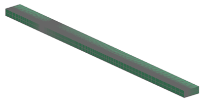
The geometry consists of a rectangular prism of 25.4 mm in height, 10 mm in width, and 381 mm in length. The prism is partitioned along the length to give two sections, one of 76.2 mm and the other of 304.8 mm.

Simulation model
The swept mesh is made of hexahedral elements. The following mesh controls are used:
- Height: 50 elements, 0.94 bias
- Width: 2 elements
- Length, fore section: 30 elements, 0.9 bias
- Length, aft section: 100 elements, 0.97 bias
The fluid is modeled using incompressible air with the following properties:
- Mass density: ρ = 0.3706 kg/m3
- Thermal conductivity: k = 0.0263 W/m·°C
- Dynamic viscosity: µ = 1.85e-005 Pa·s
- Specific heat at constant pressure: Cp = 1007 J/kg·K
The gas constant is kept blank to simulate a truly incompressible flow.
The following boundary conditions are applied:
- Flow Boundary Condition: Inlet Flow on the front of the prism with a velocity of 39.5 m/s and ambient external conditions.
- Flow Boundary Condition: Outlet Flow on the top of the prism with a velocity of 2.7 m/s. This value has been determined iteratively so that the velocity’s linear deceleration happens in a downstream section of the model.
- Flow Boundary Condition: Opening on the back of the prism with an ambient external conditions.
- Flow Surface: Boundary Flow Surface with the Slip Wall option on the bottom surface of the fore section.
- Flow Surface: Boundary Flow Surface with the No Slip Wall option and the Smooth - With Friction option on the bottom surface of the aft section.
- Symmetry Plane on the right and left surfaces.
- Modeling Objects: Planar Head Loss with a head loss coefficient of 10.
- Modeling Objects: Turbulence Characteristics with turbulent intensity of 0.04 and eddy length of 0 mm.
The following solution options are set:
- Turbulence Model:None (Laminar Flow)
- Ambient conditions: Ambient pressure = 41.4 kPa, ambient fluid temperature = 115.7 °C
- Initial Conditions: Lengthwise velocity = 39.5 m/s, a pressure = 41.4 kPa, a fluid temperature = 115.7 °C
The following solver parameters are selected:
- 3D Flow Solver: Physical steady-state Time Step: 0.01 s
- 3D Flow Solver: Maximum Residuals = 1e-6
- 3D Flow Solver: Momentum Advection Scheme: SOU with specify factor of 0.5
- 3D Flow Solver: Mass Relaxation Factor: 0.25
Theory
The theory of Howarth [29] is used as a basis of comparison for the solver results. In particular, the friction coefficient can be expressed as a polynomial series (nine terms of the series is sufficient):
where:
- Cf,x is the friction coefficient.
- Cf,x(dU/dx = 0) is the friction coefficient with constant free stream velocity (Blasius solution).
The Blasius solution is given by:
and
The friction coefficient, Cf, is determined using the shear stress extracted along one of the plate edges, and U is approximated based on the linearly decelerating average velocity across the domain and defined as:
Results
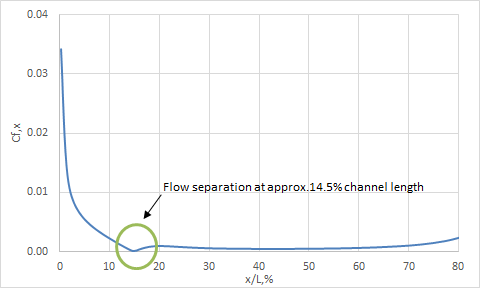
The friction coefficient results are presented in the following figure.

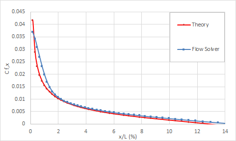
Friction coefficient via percent plate length before separation is displayed in the following figure.

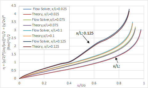
The velocity profiles at various plate positions are represented in the following figure.

Finally, the separation point predicted by solver is close to x/L = 0.145, while that of Howarth’s solution is at x/L = 0.125.
