VVF20 - Volume flow recovery of an internal fan
| Flow boundary conditions | Test case |
|---|---|
| Case1 | SVTEST201 |
| Case2 | SVTEST202 |
| Case3 | SVTEST203 |
Description
This test case examines the volume flow recovery for three configurations, A, B, and C, of a channel with an internal fan and various screen scenarios. The fan curve for cases A, B, and C is extracted from the paper [22].
Geometry
The channel is 770 mm in length, 38 mm in height and, 38 mm in width as shown in the following figure. The channel has 2 openings (1) and (4). The internal fan (3) is located at 390 mm from the opening (1) and the screen (2) is positioned at 10 mm in front of the fan.
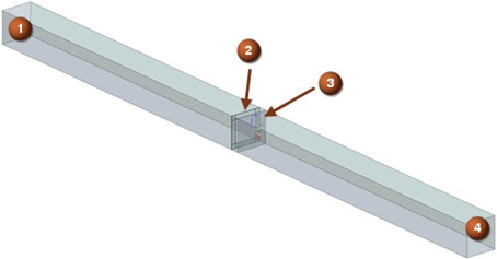
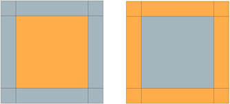
In case A, there is no screen placed in front of the internal fan. In case B, the screen is perforated in the area that is facing the hub of the fan. In case C, the screen is perforated in the area that is facing the tip of the fan.
Simulation model
This model uses the Advanced Flow solution type.
The channel is meshed using a structured hexahedral mesh with 5 mm elements size.
The fluid is modeled using incompressible air with the following properties:
- Mass density: ρ = 1.207 kg/m3
- Thermal conductivity: k = 0.0263 W/m·K
- Dynamic viscosity: µ = 1.85e-005 kg/m·s
- Specific heat at constant pressure: Cp = 1007 J/kg·K
- Coefficient of thermal expansion: β = 3.41e-006 m/K
- Gas constant: R = 287 J/kg·K
The following boundary conditions are applied:
- Flow Boundary Condition: Opening on the inlet end (1) of the channel
- Flow Boundary Condition: Opening on the outlet end (4) of the channel with the pressure difference between the two openings of 50 Pa
- Flow Boundary Condition: Internal Fan on the position (3)
- Screen on the position (2)
The position of boundary conditions is presented in the figure above.
In case A, there is no screen imposed in the model. The selections for the screen in cases B and C are shown in the following figure. Slip Wall is assigned on all other walls.
The following non-default solution options are used:
- Turbulence Model: None (Laminar Flow)
- Solution Type:Steady State
The following solver parameters are selected:
The following non-default solver parameters are used:
- 3D Flow Solver: Time Step = 0.1 for cases A and B and 0.05 for case C
- 3D Flow Solver: Maximum Residuals = 1e-6
Results
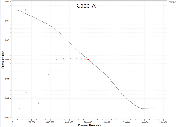
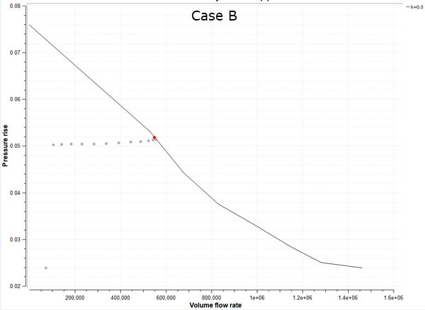
The solver recovers the operating point for all three cases as seen in the following figures.
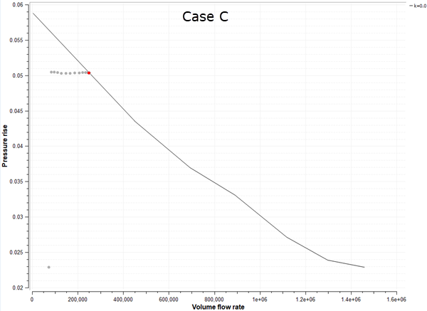
The following table lists the volume flow rate at a pressure rise of 50 Pa for all three configurations.
| Parameter | Case A | Case B | Case C |
|---|---|---|---|
| Volume flow rate, mm3/s | 800.33 | 548.46 | 249.71 |
