VVF4 - Incompressible laminar non-Newtonian flow in a pipe
| Power-Law | Herschel-Bulkley | Carreau | |||
|---|---|---|---|---|---|
| Power law index | Test case | Power law index | Test case | Power law index | Test case |
| 0.1 | SVTEST125 | 0.2 | SVTEST145 | 0.1 | SVTEST155 |
| 0.2 | SVTEST126 | 0.4 | SVTEST146 | 0.25 | SVTEST156 |
| 0.3 | SVTEST127 | 0.6 | SVTEST147 | 0.5 | SVTEST157 |
| 0.4 | SVTEST128 | 0.8 | SVTEST148 | 0.75 | SVTEST158 |
| 0.5 | SVTEST129 | 1.0 | SVTEST149 | 1.0 | SVTEST159 |
| 0.6 | SVTEST130 | 1.2 | SVTEST150 | 1.25 | SVTEST160 |
| 0.7 | SVTEST131 | 1.4 | SVTEST151 | 1.5 | SVTEST161 |
| 0.8 | SVTEST132 | 1.6 | SVTEST152 | 1.75 | SVTEST162 |
| 0.9 | SVTEST133 | 1.8 | SVTEST153 | 2.0 | SVTEST163 |
| 1.0 | SVTEST134 | 2.0 | SVTEST154 | ||
| 1.1 | SVTEST135 | ||||
| 1.2 | SVTEST136 | ||||
| 1.3 | SVTEST137 | ||||
| 1.4 | SVTEST138 | ||||
| 1.5 | SVTEST139 | ||||
| 1.6 | SVTEST140 | ||||
| 1.7 | SVTEST141 | ||||
| 1.8 | SVTEST142 | ||||
| 1.9 | SVTEST143 | ||||
| 2.0 | SVTEST144 | ||||
Description
This case examines the incompressible, laminar flow of a non-Newtonian fluid in a cylindrical pipe with a fluid viscosity that varies with shear rate according to the following models:
Power-Law, for ηmin<η<ηmax.
Herschel-Bulkley, for ̇γ>σintersect /μ0
Carreau
where:
- η is the fluid viscosity.
- K is the consistency index.
- ̇γ is the shear rate.
- n is the power law index.
- T0 is the reference temperature.
- T is the fluid temperature.
- ηmin is the minimum viscosity limit.
- ηmax is the maximum viscosity limit.
- σ0 is the yield stress.
- σintersect is the shear stress.
- μ0 is the yield viscosity.
- ɳ∞ is the infinite-shear viscosity.
- η0 is the zero-shear viscosity.
- λ is the time constant.
The influence of the power law index on the wall shear stress and velocity profiles at the end of the pipe are compared using the Rabinowitsch-Mooney equation.
Geometry
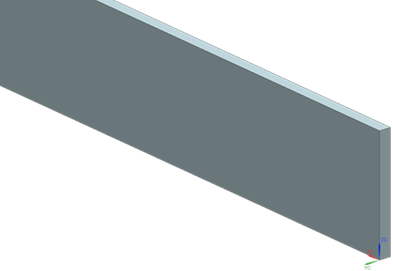
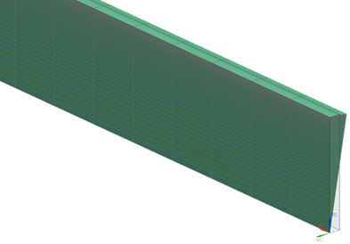
The geometry consists of a rectangle of 2000 mm in length and 20 mm in height. The X axis is defined to be 0.01 mm in the -Z direction from the lower edge of the rectangle to avoid wedge elements in the inner part of the arc pipe. The figure below shows the geometry used to create the pipe mesh and its position relative to the global coordinate system.
Simulation model
This model uses the Advanced Flow solution type.
The X-Z surface of the rectangle is meshed using a mesh of quadrilateral elements. The following mesh controls are used on the surface of the rectangle:
- Height: 50 elements, 1.06 bias
- Length: 200 elements, no bias
The revolved mesh creates the arc pipe using hexahedral elements. The following settings are used:
- Number of copies: 2
- Axis of revolution: X axis
- Angle: 5º per copy
The following figure shows the generated mesh.
The fluid is modeled using water with the following properties:
- Mass density: ρ =1000 kg/m3
- Thermal conductivity: k = 0.603 W/m·C
- Dynamic viscosity: µ = 1.006e-3 Pa·s
- Specific heat at constant pressure: Cp = 4187 J/kg·K
In addition to this fluid, several non-Newtonian fluid modeling objects with varying power law indices are created. The following properties are used for runs with the Power-Law model:
- Consistency index: K =1.006e-3 Pa-sn
- Reference temperature: T0 = 0º
- Minimum viscosity limit: ηmin= 0 kg/mm·s
- Maximum viscosity limit: ηmax= 10000 kg/mm·s
The following properties are used for runs with the Herschel-Bulkley model:
- Yield stress: σ0 = 1.006e-3 Pa
- Consistency index : K = 1e-3 Pa·sn
- Yield viscosity: µ0 = 5e-3 Pa·s
The following properties are used for runs with the Carreau model:
- Time constant: 1 s
- Reference temperature: T0 = 0º
- Zero shear viscosity: η0 = 0.00228 kg/m·s
- Infinite shear viscosity: η∞ = 0.001 kg/m·s
The reference temperature is set to zero in order for the Power-Law and Carreau relations to be temperature independent.
The following boundary conditions are used for all fluid viscosity relations:
- Flow Boundary Condition: Inlet Flow on the front of the arc pipe with a volume flow rate Q = 2e-5 m3/s and ambient external conditions
- Flow Boundary Condition:Opening on the back of the arc pipe with ambient external conditions
- Flow Surface: Boundary Flow Surface on the top of the arc pipe using a No Slip Wall condition with smooth wall friction
- Flow Surface:Boundary Flow Surface on the radial walls and the bottom of the arc pipe using a Slip Wall
The following solution options are set:
- Turbulence Model : None (Laminar Flow)
The appropriate non-Newtonian fluid modeling object is selected in the additional parameters group on the 3D Flow page.
For each non-Newtonian model, multiple steady-state solutions are solved. Each solution has a different power law index and physical steady state time step listed in the following table.
| Power-Law | Herschel-Bukly | Carreau | |||
|---|---|---|---|---|---|
| n | time step | n | time step | n | time step |
| 0.1 | 1 | 0.2 | 0.2 | 0.1 | 0.5 |
| 0.2 | 1 | 0.4 | 0.5 | 0.25 | 0.5 |
| 0.3 | 1 | 0.6 | 0.5 | 0.50 | 0.5 |
| 0.4 | 1 | 0.8 | 0.5 | 0.75 | 0.5 |
| 0.5 | 1 | 1.0 | 0.4 | 1.0 | 0.5 |
| 0.6 | 1 | 1.2 | 0.3 | 1.25 | 0.5 |
| 0.7 | 1 | 1.4 | 0.2 | 1.50 | 0.5 |
| 0.8 | 1 | 1.6 | 0.2 | 1.75 | 0.2 |
| 0.9 | 1 | 1.8 | 0.2 | 2.0 | 0.2 |
| 1.0 | 1 | 2.0 | 0.2 | ||
| 1.1 | 0.5 | ||||
| 1.2 | 0.4 | ||||
| 1.3 | 0.3 | ||||
| 1.4 | 0.3 | ||||
| 1.5 | 0.2 | ||||
| 1.6 | 0.1 | ||||
| 1.7 | 0.1 | ||||
| 1.8 | 0.1 | ||||
| 1.9 | 0.1 | ||||
| 2.0 | 0.1 | ||||
The following table lists other non-default 3D flow solver parameters that were set for the solutions of the different non-Newtonian models.
| Parameter | Power- Law | Herschel-Bulkley | Carreau |
|---|---|---|---|
| RMS residuals | 1e-10 | 1e-5 | 1e-6 |
| Iteration limit | 10000 | 10000 | 1000 |
Theory
For an incompressible non-Newtonian fluid, the relation between the shear stress and shear rate is defined as:
where:
- σ is the shear stress.
- ɳ is defined in equations.
- ̇γ is the shear rate.
The Rabinowitsch-Mooney Equation [9] is used as a basis to compare the solver results. Notably, the equation gives a relation between volumetric flow rate Q, the tube radius R, the wall shear stress σw and the shear rate f(σ) = ̇γ as follows:
In a fully-developed pipe, the shear rate can be expressed as:
where:
- u is the axial velocity component.
- r is a cylindrical coordinate component.
Additionally, for fully-developed laminar flow in a pipe, the shear stress distribution throughout the pipe can be written as a linear function of the radius:
Substituting r from the share stress equation in the share rate equation, it is possible to numerically integrate for the axial velocity u at the end of the pipe.
Results
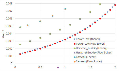
The following figure compares the influence of the power law index on the wall shear stress at the end of the pipe for the Power-Law, Herschel-Bulkley, and Carreau models.
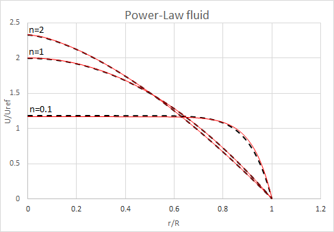
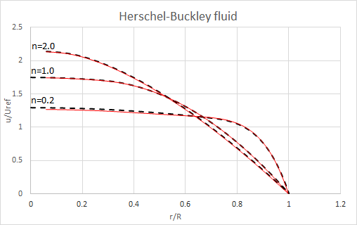
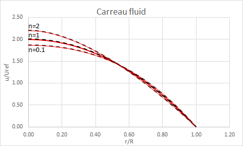
The following figures present laminar, fully-developed velocity profiles for Power-Law, Herschel-Bulkley and Carreau fluid for different values of power law indices. The inlet velocity Uref is computed using the following equation:
