VVF5 - Incompressible laminar flow in a pipe (Hagen-Poiseuille flow)
| Test case |
|---|
| SVTEST164 |
Description
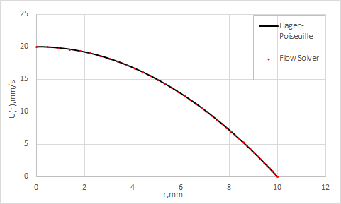
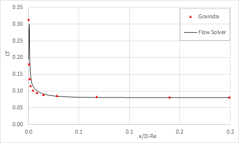
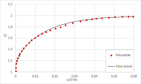
This test case examines the incompressible laminar viscous flow in a circular pipe (HagenPoiseuille flow). The flow enters the pipe with a constant velocity profile and develops into a parabolic profile in the entrance region. The fully-developed velocity profile at the end of the pipe is compared to the Hagen-Poiseuille solution. Furthermore, the centerline velocity in the entry region is compared to experimental data from Nikuradse. Finally, the skin friction coefficient along the pipe’s length is compared with Govinda’s correlation.
Geometry
The geometry consists of a 30º section of a cylinder. The cylinder has a diameter of 20 mm and a total length of 2500 mm. The cylinder section is partitioned along its length to give a 500 mm section and a 2000 mm section.
Simulation model
The swept mesh is made of hexahedral elements. The following mesh controls are used:
- Radius: 40 elements, 1.035 bias
- Cylinder’s arc: 3 elements, 5º each
- Length, fore section: 125 elements, no bias
- Length, aft section: 500 elements, no bias
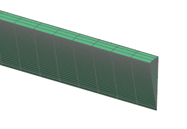
The following figure shows the generated mesh.

The fluid is modeled using water with the following properties:
- Mass density: ρ = 1000 kg/m3
- Thermal conductivity: k = 0.6033 W/m·C
- Dynamic viscosity: µ = 1.006e-003 Pa·s
- Specific heat at constant pressure: Cp = 4182 J/kg·K
The following boundary conditions are used:
- Flow Boundary Condition: Inlet Flow on the front of the fore section of the pipe with inlet velocity of 0.01 m/s.
- Flow Boundary Condition:Opening on the back of the fore section of the pipe with ambient external conditions.
- Flow Surface: Boundary Flow Surface on the outer surface of the 500 mm fore section of the cylinder using a Slip Wall with convection properties set to No Convection-Adiabatic.
-
Flow Surface: Boundary Flow Surfaceon the outer surface of the 2000 mm fore section of the cylinder.
- Wall Treatmentis set to the No Slip Wallcondition with smooth wall friction.
- Periodic Boundary Condition: Rotational Periodicity on the right and left surfaces of both sections of the pipe.
- Turbulence Model:None (Laminar Flow)
- Initial Conditions: Lengthwise velocity of 0.01 m/s
The following solver parameters are set:
- 3D Flow Solver: Time Step = 0.5 s
- 3D Flow Solver: Maximum Residuals = 1e-8
- 3D Flow Solver:Mass relaxation factor = 0.25
Theory
The Hagen-Poiseuille solution [10] of the fully-developed laminar velocity profile is used as a basis of comparison for the solver.
where:
- Uavg is the inlet velocity.
- R is the radius of the pipe.
- u is the axial velocity component.
- r is the radius along the pipe.
This result is a particular solution of the momentum equation where we consider the flow to be purely axial Ur = Uθ = 0.
Govinda, Ramamorthy and Sarma [11] have shown that the wall shear stress can be expressed as:
where:
- K is the ratio of core velocity to the inlet velocity.
- τw is the shear stress.
- μ is the water dynamic viscosity.
A list of values of K has been numerically integrated by Astana and is presented in the table.
| K | 1 | 1.1 | 1.2 | 1.3 | 1.4 | 1.5 | 1.6 | 1.7 | 1.8 | 1.9 | 2 |
|---|---|---|---|---|---|---|---|---|---|---|---|
| 0 | 6.1e-5 | 3.4e-4 | 9.9e-4 | 2.2e-3 | 4.4e-3 | 8.2e-3 | 1.5e-2 | 2.8e-2 | 6.8e-2 | ∞ |
The skin friction coefficient is then computed using the following definition:
Results
The velocity profile results are presented in the following figure.

The skin friction coefficient results are presented in the following figure.

The last figure compares the center line velocity in the entry region to experimental data from Nikuradse [11].

