VVF16 - Incompressible laminar backward-facing step
| Test case |
|---|
| SVTEST194 |
Description
This test case examines the steady, incompressible, laminar flow over a backward-facing step for a Reynolds number (based on the hydraulic diameter of the inlet channel: Dh = 2h) of 800. This problem displays flow separation and reattachment of boundary layers, and is especially useful in the examination of out flow boundary conditions.
Geometry
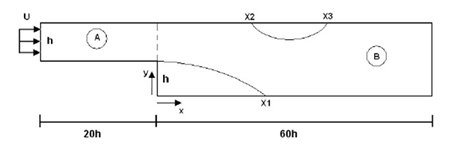
The geometry is made up of two extruded rectangular sections: A and B.
Section A: 200 mm (+ X-dir) x 10 mm (+ Y-dir) x 1 mm (+ Z-dir)
Section B: 600 mm (+ X-dir) x 20 mm (+ Y-dir) x 1 mm (+ Z-dir)
The height of the entrance channel is 10 mm, which results in a hydraulic diameter of 2h = 20 mm.

Simulation model
This model uses the Advanced Thermal-Flow solution type.
The swept mesh is made of hexahedral elements.
For section A
- 400 elements along the +X-dir; end of edge bias ratio = 0.997; edge fraction = 1
- 61 elements along the +Y-dir; no bias
- 2 elements along the +Z dir; no bias
For section B
- 800 elements along the rst half of section B (0 − 30h) in the + X-dir; no bias (uniform)
- 400 elements along the second half of section B (30 − 60h) in the + X-dir; end of edge bias ratio = 0.997; edge fraction = 1
- 61 elements along the +Y-dir; no bias
- 2 elements along the +Z-dir; no bias
Total number of elements in the model is ∼ 195 K.
Total number of nodes in the model is ∼ 518 K.
The fluid is modeled using incompressible air with the following properties:
- Mass density: ρ = 1.0 kg/m3
- Dynamics viscosity: µ = 2.0 x 10⁻⁶ Pa·s
- Specific heat at constant pressure: Cp = 1 J/kg·K
The gas constant was kept blank in order to simulate a truly incompressible flow.
The following boundary conditions are applied:
- Symmetry Plane on the +Z-dir and −Z-dir walls
- Flow Surface: Boundary Flow Surface on the top (+Y-dir) and bottom (− Y-dir) walls of sections A and B using No Slip Wall conditions
- Flow Boundary Condition: Inlet on the left side of section A (− X-dir) with velocity U = 80 mm/s
- Flow Boundary Condition: Opening on the right side of section B (+ X-dir)
The following solution options are set:
- Turbulence Model:None (Laminar Flow)
The following solver parameters are selected:
- 3D Flow Solver: Maximum Residuals = 1e-5
- Advection Schemes Momentum: Second-order (CDS)
- Limiter: Automatic; Momentum Limiter Stabilization: General Convective Boundedness Condition
Theory
The steady, laminar, incompressible flow over a backward-facing step provides an example of flow separation and reattachment of boundary layers. This problem has been studied extensively, both experimentally and numerically, in the literature [19], [20].
Results
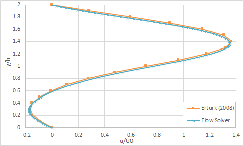
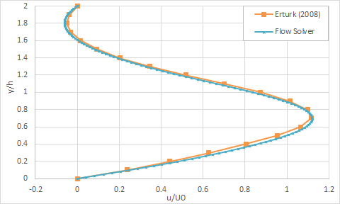
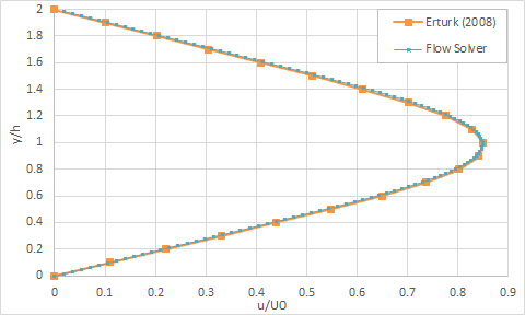
The following section presents cross-channel velocity profiles at different streamwise stations downstream of the step. The following figures display cross-channel velocity profiles (u/U):
x/h = 6
- (u/U)max ∼ 1.3663 at y/h = 1.4 from Erturk (2007) [20]
- Percent error in (u/U)max value between the flow solver and literature is 0.95 % x/h

x/h = 14
- u/U)max ∼ 1.1147 at y/h = 0.7 from Erturk (2007) [20]
- Percent error in (u/U) max value between the flow solver and literature is 0.58 % x/h

x/h = 30
- (u/U)max ∼ 0.8503 at y/h = 1.0 from Erturk (2007) [20]
- Percent error in (u/U)max value between the flow solver and literature is 0.09 %

The schematic representation of the points of interest listed in the following table.
| Parameter | x/h | Error (% | |
|---|---|---|---|
| Point of interest | Flow solver | Erturk (2008) [20] | Flow solver |
| X1 | 10.69 | 11.834 | 9.7 |
| X2 | 8.48 | 9.476 | 10.5 |
| X3 | 20.21 | 20.553 | 1.7 |
The following figure displays sample velocity contours of the backward-facing step problem.

