VVF21 - Incompressible turbulent flow over a flat plate with zero pressure gradient
| Mesh size | Solution | Test case |
|---|---|---|
| 35x25 | SA- Spalart-Allmaras | SVTEST204 |
| 35x25 | SST-Shear Stress Transport | SVTEST205 |
| 69x49 | SA- Spalart-Allmaras | SVTEST206 |
| 69x49 | SST-Shear Stress Transport | SVTEST207 |
| 137x97 | SA- Spalart-Allmaras | SVTEST208 |
| 137x97 | SST-Shear Stress Transport | SVTEST209 |
| 273x193 | SA- Spalart-Allmaras | SVTEST210 |
| 273x193 | SST-Shear Stress Transport | SVTEST211 |
| 545x385 | SA- Spalart-Allmaras | SVTEST212 |
| 545x385 | SST-Shear Stress Transport | SVTEST213 |
Description
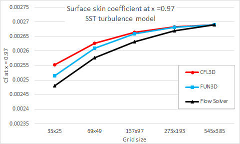
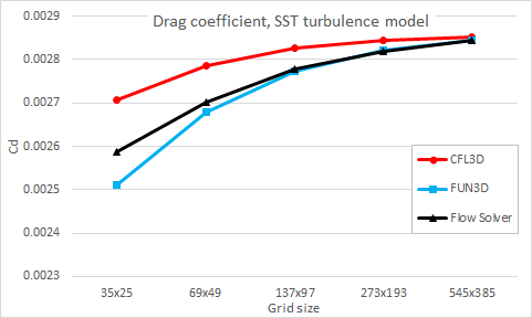
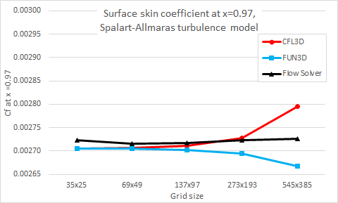
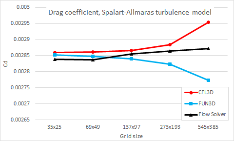
This validation case investigates the incompressible turbulent flow over a flat plate with a zero pressure gradient for two types of turbulence models: Shear Stress Transport (SST) and Spalart-Allmaras. The drag and surface skin friction coefficients results that ther solver computes are compared with the NASA CFD results [45].
Geometry
The geometry consists of a rectangle of 2333 mm in length, 1000 mm in height, and 1000 mm in width. The same geometry is used for both the SST and Spalart-Allmaras turbulence models.
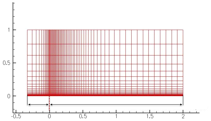
The following figure shows a simple plate layout [46]. The plate extends from x=0 to x=2.
Simulation Model
This model uses the Advanced Flow solution type.
The mesh used in this validation case is a series of five 3D grids, of the same family, ranging from the finest to coarsest grid. This grid is created in the PLOT3D format defined by the NASA Langley Research Center [46]. After the grid is imported, the model includes only a single layer of 3D hexahedral elements. To obtain results that are similar to 2D results, the imported mesh is split into two element layers along Y direction, as shown in the following figure.
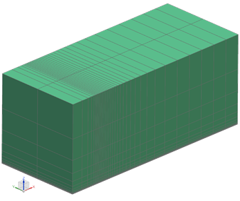
The element length along the Y direction for each layer is 500 mm.
The following table represents the mesh characteristics. The X, Y, and Z columns list the number of elements in each direction.
| Mesh size | X | Y | Z | Total number of elements |
|---|---|---|---|---|
| 35x25 | 34 | 2 | 24 | 1632 |
| 69x49 | 68 | 2 | 48 | 6528 |
| 137x97 | 136 | 2 | 96 | 26112 |
| 273x193 | 272 | 2 | 192 | 104448 |
| 545x385 | 544 | 2 | 384 | 417792 |
The fluid is modeled using incompressible air with the following properties:
- Mass density: ρ = 1.33 kg/m3
- Gas constant: R = 286.90 J/kg · K
- Dynamic viscosity: µ = 1.85 × 10⁻⁵ kg/m · s, based on Sutherland's law at Tref = 300 K
- Speed of sound: aref = (γ·R·Tref)0.5 = 347.19 m/s
- Specific heat ratio of air: γ = 1.4
- Kinematic viscosity: ν = L (aref M)/ Re = 1.39 × 10⁻⁵ m2/s
- Mach number: M = 0.2
- Reynolds number: Re = 5 × 10⁶
The gas constant is kept blank to simulate a truly incompressible flow.
The following boundary conditions are applied:
- Flow Boundary Condition: Inlet Flow on the front of the prism with a velocity of Uref = 69.44 m/s (129.6 ft/s) with specified external conditions.
-
Flow Boundary Condition: Static Pressure on the top of the prism with specified external conditions.
- Flow Boundary Condition: Static Pressure on the opposite side to the inlet with external conditions set to ambient.
- Flow Surface: Boundary Flow Surface on the bottom from x= – 0.35 to x=0 using a Slip Wall condition.
- Flow Surface: Boundary Flow Surface on the bottom from x=0 to x=2 using No Slip Wall condition.
- Symmetry Plane on the +Y-dir and -Y -dir walls.
- Modeling Objects: Turbulence Characteristics with K-Omega, a turbulent kinetic energy (1.125·Uref)2/Re = 1084.86 mm2/s2, a specific dissipation rate (125·Uref)2/Re = 8679.71773734607 sec−1
For every boundary condition with the external conditions, use the Turbulence Characteristics modeling object.
The following solution options are set:
- Turbulence Model: SST-Shear Stress Transport for SST model, SA- Spalart-Allmaras for Spalart-Allmaras model.
- Solution Type: Steady State.
- Ambient Conditions: Absolute pressure value = 0.1147 MPa, fluid temperature = 300K.
- Initial Conditions: X, Y, Z velocity = 0 m/s.
The following solver parameters are selected:
- 3D Flow Solver: Physical steady-state with time step = 0.0001 s
- 3D Flow Solver: RMS Residuals = 1e-8
- 3D Flow Solver: Iteration limit = 2000
Theory
The NASA CFD results are provided from two compressible codes: cell-centered structured-grid (CFL3D) and node-centered unstructured-grid (FUN3D) codes, that compute the zero-pressure-gradient flat plate flow with the Menter shear stress transport model. Both codes use Roe's Flux Difference Splitting and a UMUSCL upwind approach. In the CFL3D code, the standard UMUSCL (kappa=0.33333) scheme is used, and in the FUN3D code the option UMUSCL= 0.5 is used. Both codes are run with full Navier-Stokes and both codes use first-order upwinding for the advective terms of the turbulence model. Multiple grids are used to identify trends with grid refinement [45], [46], [47].
Results
The following figures compare the flow solver results with the NASA CFD results for the wall skin friction at x = 0.97008 and the drag coefficient with a grid size for both SST and Spalart- Allmaras turbulence models.
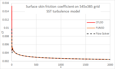
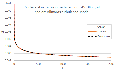
The following figures compare the flow solver results with the NASA CFD results for the surface skin friction coefficient on the finest 545x385 grid, over the entire plate for SST and Spalart-Allmaras turbulence models.
