VVF6 - Low-speed turbulent flow over a backward-facing step
| Solution | Test case |
|---|---|
| K-Omega | SVTEST165 |
| SST-Shear Stress Transport | SVTEST166 |
Description
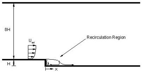
This case examines the incompressible flow over a backward-facing step using the turbulence models SST and k-ω. The U velocity profiles in the recirculating region and the evolution of the skin friction coefficient along the bottom of the volume control are compared with experimental results of Drive and Seegmiller [30]. The following figure [31] presents the modeled flow.
Geometry
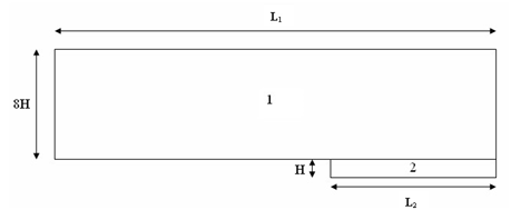
The geometry consists of two rectangular prisms. The first prism has a height of 8H = 101.6 mm, a length of L1 = 1968.5 mm, and a width of 15.1 mm. The second prism has a height of H = 12.7 mm, a length of L 2 = 635 mm, and a width of 15.1 mm. The first prism is partitioned along its length to give two sections: 1333.5 mm and 635 mm. The following figure represents the geometry with a step height to the tunnel exit height ratio of 1:9. It minimizes the freestream pressure gradient due to the sudden expansion.
Simulation model
This model uses the Advanced Flow solution type.
The swept mesh is made of hexahedral elements. The following mesh controls are used on the first prism:
- Height: 230 elements, bias origin at center of edge, 1.04 bias
- Width: 2 elements
- Length, fore section: 120 elements, 1.03 bias
- Length, aft section: 80 elements, 1.04 bias
The following mesh controls are used on the second prism:
- Height, fore section: 130 elements, bias origin at center of edge, 1.04 bias
- Width: 2 elements
- Length: 80 elements, 1.04 bias
The fluid is modeled using air with the following properties:
- Mass density: ρ = 1.207 kg/m3
- Thermal conductivity: k = 0.0263 W/m·C
- Dynamic viscosity: µ = 1.85e-005 Pa·s
- Specific heat at constant pressure: Cp = 1007 J/kg·K
- Gas constant: R = 287 J/kg·K
The following boundary conditions are applied:
- Flow Boundary Condition: Inlet Flow on the front of the fore section of the prism with a velocity of 44.2 m/s, external conditions set to ambient, and turbulence characteristics set to turbulent kinetic energy = 0.293 m2/sec2, a specific dissipation rate = 17411933 sec−1
- Flow Boundary Condition: Opening on the back of the aft section of the prism.
- Flow Surface: Boundary Flow Surface on the bottom and top surfaces using a No Slip Wall condition with smooth wall friction and the convection properties set to No Convection-Adiabatic.
- Symmetry Plane on the right and left surfaces
- Modeling Objects: Turbulence Characteristics with a turbulent kinetic energy = 0.293 m2/sec2, a specific dissipation rate = 17411933 sec−1
The following non-default solver options are used for the run with k-ω:
- Turbulence model: k-Omega
- Initial conditions: Lengthwise velocity = 44.2 m/s
The following non-default solver options are used for the run with SST:
- Turbulence model: Shear Stress Transport-SST
- Initial conditions: Lengthwise velocity = 44.2 m/s
The following non-default solver parameters are used for both runs:
- 3D Flow Solver : Physical steady-state with time step = 0.001 s
- 3D Flow Solver: RMS Residuals = 2e-6
- Mass Relaxation Factor: 0.25
Theory
The low-speed turbulent flow over a backward-facing step has been studied extensively, both experimentally and numerically, in the literature [30], [31] .
Results
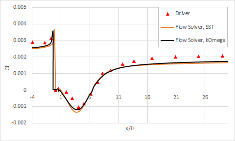
The following figure compares the evolution of the skin friction coefficient along the bottom surface.
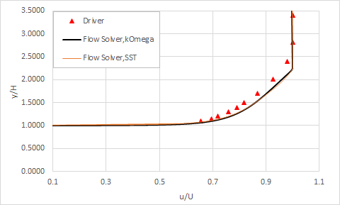
The following figures show the velocity profiles at four axial locations, just before and in the recirculating region. All of the profiles are normalized by the flow velocity just before the back step ( Uref= 46.5 m/s).
Velocity profile at x/H=-4:
Velocity profile at x/H=1.5:
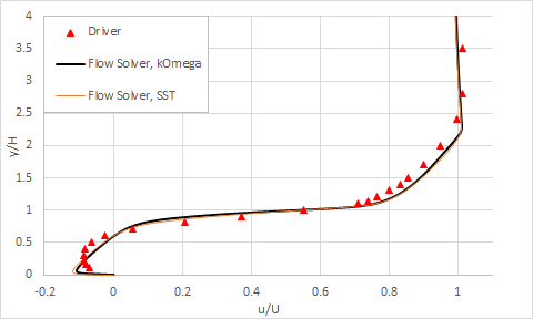
Velocity profile at x/H=2.5:
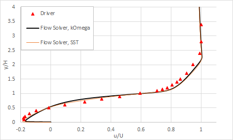
Velocity profile at x/H=5.0:
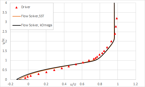
The reattachment point measured experimentally is x/H = 6.279, whereas solver SST predicts a reattachment point at x/H = 6.508 and k-Omega at x/H = 6.123, where x is the lengthwise coordinate and H is the step height.
