VVF17 - Incompressible laminar flow over cylinder
| Test case |
|---|
| SVTEST195 |
Description
This study examines the transient (periodic-steady) laminar flow over a circular cylinder of uniform cross-section. A Reynolds number of 150, based on the diameter, is used in this model. This Reynolds number is selected as it corresponds to a two-dimensional flow and has periodic vortex shedding capabilities.
Geometry
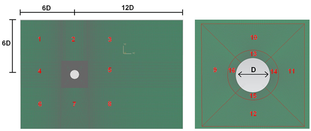
The geometry consists of an extruded rectangular fluid domain with a cylindrical cavity as shown in the following figure. The diameter (D) of the cylindrical cavity is 100 mm. The length of the calculation domain in the Z-dir is 10 mm.
Simulation model
This model uses the Advanced Thermal-Flow solution type.
The swept mesh is made of hexahedral elements. The calculation domain is partitioned into 16 sections as shown in the previous figures. The following mesh controls are used:
| Section | Position | Number of elements | Bias factor |
|---|---|---|---|
| 1 and 6 | X | 70 | start edge=0.98 with edge fraction=1 |
| 1 and 6 | Y | 90 | no |
| 2 and 7 | X | 70 | center edge=1.02 |
| 2 and 7 | Y | 90 | no |
| 3 and 8 | X | 120 | start edge=0.985 with edge fraction=1 |
| 3 and 8 | Y | 90 | no |
| 4 | X | 70 | start edge=0.98 with edge fraction=1 |
| 4 | Y | 70 | no |
| 5 | X | 120 | start edge=0.985 with edge fraction=1 |
| 5 | Y | 70 | no |
| 9 and 11 | top and bottom | 50 | no |
| 9 and 11 | left and right sides | 70 | no |
| 10 and 12 | top and bottom | 70 | no |
| 10 and 12 | left and right sides | 50 | no |
| 13 and 15 | top and bottom | 70 | no |
| 13 and 15 | left and right sides | 20 | start edge=0.95 with edge fraction=1 |
| 14 and 16 | top and bottom | 20 | start edge=0.95 with edge fraction=1 |
| 14 and 16 | left and right sides | 70 | no |
The number of elements used in Z-dir is 2 without bias.
Total number of elements in the model: ~ 159 K.
Total number of nodes in the model: ~ 241 K.
The fluid is modeled using incompressible air with the following properties:
- Mass density: ρ = 1.0 kg/m3
- Dynamic viscosity: µ = 2.0 x 10⁻⁵ Pa·s
- Specific heat at constant pressure: Cp = 1 J/kg·K
The gas constant is kept blank in order to simulate a truly incompressible flow.
The following boundary conditions are applied:
- Symmetry Plane on the + Z-dir, – Z-dir, + Y-dir and – Y-dir walls
- Flow Boundary Condition: Inlet on the leftmost wall (- X-dir) with a velocity u = 30 mm/s
- Flow Surface: Boundary Flow Surface on the surface of the cylindrical cavity using No Slip Wall conditions
- Flow Boundary Condition: Opening on the rightmost wall (+ X-dir)
- Report: Lift and Drag on the surface of the cylindrical cavity
The following solve options are set:
- Turbulence Model: None (Laminar Flow)
- Solution Type: Transient
- Initial conditions: Uniform with the intensity of 0.04 and eddy length of 0 mm set in the Turbulence Characteristics modeling object
- Transient Setup: ∆t = 0.1 s ; total time = 500 s
- Results Sampling: Time interval 0.5 s
The following solver parameters are selected:
- 3D Flow Solver: RMS residual = 2e-05
- 3D Flow Solver: Transient iteration limit = 30
- Advection Schemes Momentum: SOU with limiter 0.5
Theory
The incompressible flow over a cylinder is defined by solving the Navier-Stokes equations:
Velocity and pressure distributions are found by previous equation. Subsequently, lift and drag coefficients are computed from the following equations:
In these equations:
- L is the lift force.
- D is the drag force.
- A is the cross-sectional area of the cylinder.
- u is the fluid velocity.
Non-dimensional numbers of Reynolds and Strouhal are defined as:
where:
- f is the frequency of vortex shedding.
- l is the characteristic length. Here, it is a diameter of the cylinder.
- v is the kinematic viscosity.
Results
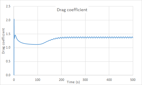
The following table shows the comparison of results pertaining to key aerodynamic parameters. The last 512 samples are used for calculation of the parameters.
| Δt (s) | Parameter | Flow solver | Theory [35] | Error (%) |
|---|---|---|---|---|
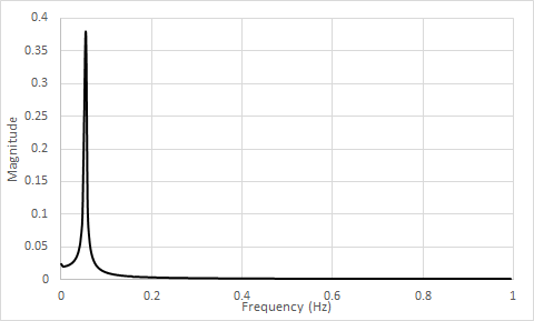
| 0.1 | St | 0.182 | 0.182 | 0 |
| CL | 0.316 | 0 +/-0.486 | 34 | |
| CD | 1.38 | 1.168+/-0.025 | 15 |
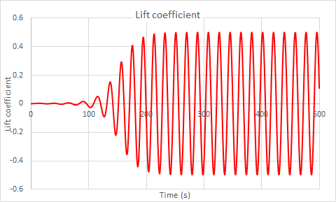
The computed Lift and Drag coefficients at Re=150 are displayed in the following figures.
The following figure shows the single-sided amplitude spectrum of Lift (t).
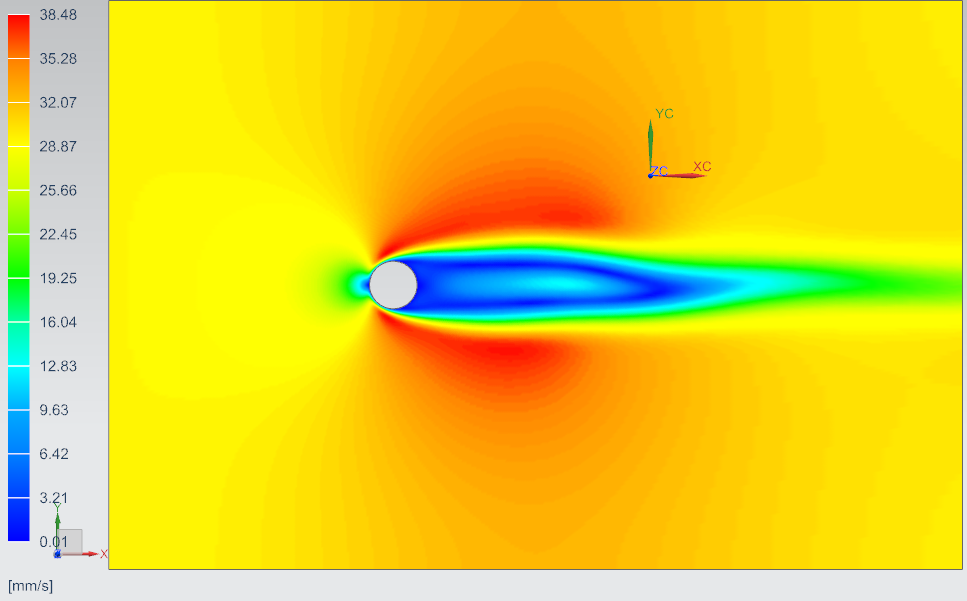
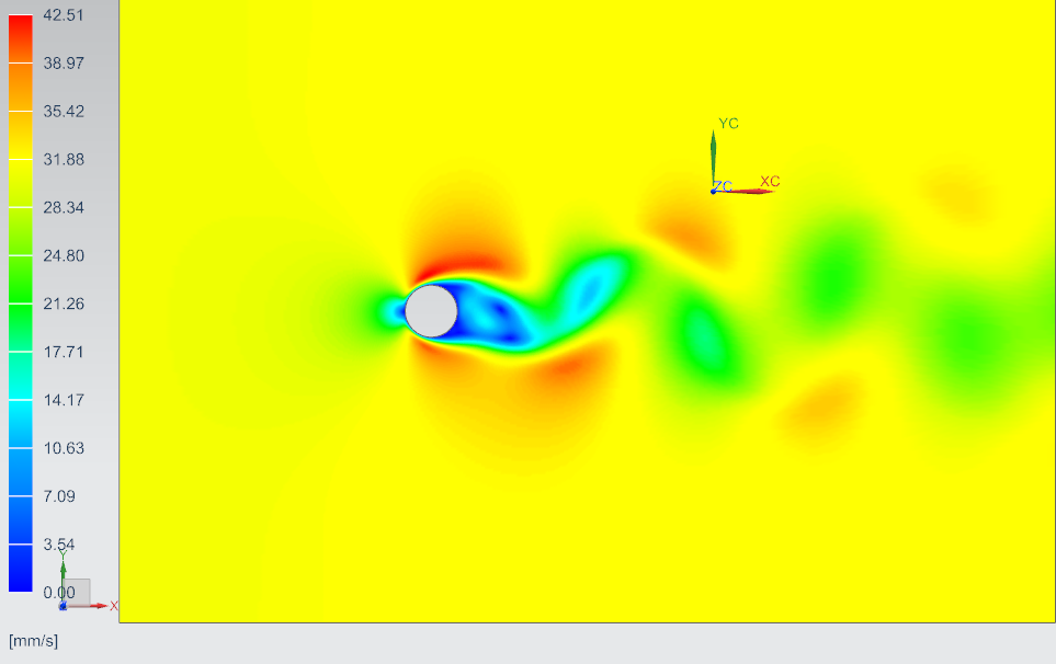
The velocity contour over the circular cylinder for Re = 150 is presented in the following figures.
