VVF14 - Slip flow regime through curvilinear microchannel
| Kn number | Test case |
|---|---|
| 0.01 | SVTEST190 |
| 0.05 | SVTEST191 |
| 0.1 | SVTEST192 |
Description
This validation case examines the slip wall boundary conditions in the curvilinear microchannel. In gas flows involving micro-channels, the Knudsen number becomes large and the slip wall boundary should be applied. In situations where the no-slip assumption is no longer valid, the velocity and the temperature of the gas next to the wall have to be adapted. The idea is to relax the traditional no-slip boundary condition to allow the rarefied gas to slip at the wall by imposing a tangential component of the slip velocity at the solid boundary. The temperature condition will also fail for non-adiabatic flows in those regimes and a temperature jump similar to a velocity slip needs to be introduced. This case compares the non-dimensional slip velocity, temperature jumps, and distance from the inlet for different Knudsen numbers with the theoretical results of Bigham and Pourhasanzadeh [49].
Geometry
The geometry consists of a micro-curvilinear channel with a constriction defined by a cosine wave. Due to symmetry conditions, the channel is split along its centerline and only half of the channel is investigated. The following figure shows half of the channel as well as the non- dimensional parameters that define the geometry.

The following equation is used to determine the non-dimensional coordinates x and y to define the curve.
where:
- A=0.15
- B=2
- 1.25 B ≤ x ≤ 2.35 B
The resulting x and y coordinate values are multiplied by the length scale of the channel, L, which represents the non-constricted channel height. The length scale, L, depends on the Knudsen number.
Simulation model
This model uses the Advanced Flow solution type.
The mesh is generated by creating a structured quad grid on the face of the geometry and sweeping this grid along the out-of-plane direction. This mesh is biased along the height direction as shown in the following figure.

The same 40 x 606 grid with 100 elements placed along the length of the constriction is used for all Kn cases.
The fluid is modeled using air with the following properties:
- Mass density: ρ = 1.207 kg/m3
- Thermal conductivity: k = 0.0263 W/m·C
- Dynamic viscosity: µ = 1.85e-005 Pa·s
- Specific heat at constant pressure: Cp = 1007 J/kg·K
- Gas constant: R = 287 J/kg·K
The following dimensionless parameters are used:
- Prandtl number: Pr=0.7
- Reynolds number: Re=2
- Knudsen number: Kn = 0.01; 0.05; 0.1
- Eckert number, corresponding to Kn: Ec = 4.82e-04; 1.21e-02; 4.82e-02
The following boundary conditions are applied:
- Flow Boundary Condition: Inlet Flow on the one end of the channel with a fixed velocity condition at x = 0 and temperature of 25 ºC specified in external conditions. (The inlet velocity depends on the Kn.)
- Flow Boundary Condition: Opening on the opposite side of the inlet at x=6.75B with an ambient pressure of 101351 Pa
- Symmetry Plane on each out-of-plane faces
- Symmetry Plane on the channel's centerline face at y =0
- Flow Surface: Boundary Flow Surface on the face defined by the curve equation 1 using a Slip Wall
- Temperature constraint on the face defined by the curve equation 1 with a value of T= 70 ºC
The following solution options are set:
- Turbulence Model: None(Laminar Flow)
- Solution Type: Steady State
- Ambient Conditions: Fluid temperature = 25 ºC
The following advanced parameters are selected:
USE LOW-PRESSURE MAXWELL SLIP WALL TREATMENT-
USE LOW-PRESSURE MAXWELL TEMPERATURE JUMP TREATMENT -
INCLUDE THERMAL CREEP TERM IN MAXWELL MODEL -
OUTPUT LOW-PRESSURE MAXWELL SLIP WALL SUMMARY -
INCLUDE_VISCOUS_HEATING -
MAXWELL SLIP WALL C1: 1.22 -
MAXWELL SLIP WALL SIGMA T: 0.9
In addition, the following advanced parameters are added through the user.prm file:
-
GRADIENT_BOUNDARY_TREATMENT_VEL: 1 -
GRADIENT_BOUNDARY_TREATMENT_PRESS = 1 -
USE_NODAL_MAXWELL_SLIP_VALS = TRUE MEAN_FREE_PATH_LAMBDA:X, where X is a constant free mean path corresponding to the particular Kn case.-
LOW_PRESSURE_SLIP_WALL_CV: 719.3 -
RELAX_LOW_PRESSURE_SLIP_WALL: 0.1
The first three parameters activate the nodal wall treatment for velocity and pressure. The last three parameters treat the gas with a constant density and a fixed value for the mean free path of the gas.
The following solver parameters are selected:
- 3D Flow Solver: Physical steady-state with time step = 0.01 s
- 3D Flow Solver: RMS Residuals = 1e-10
- Momentum advection scheme: SOU with automatic limiter
Theory
Bigham and Pourhasanzadeh [49] use a value of 0.9 for the fraction of diffusely reflected molecules σv. The corresponding value for the first order slip coefficient, C1, can be calculated using the following equation:
Results
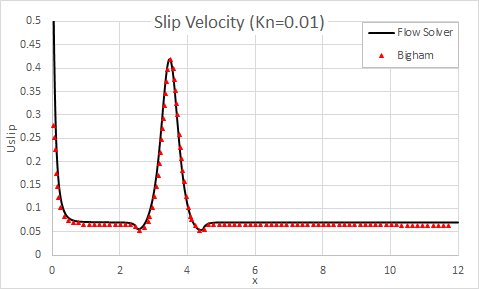
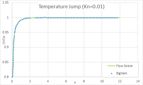
The following figures show the comparison of the flow solver results with theoretical results for the slip velocity and temperature jump results for the Kn=0.01.
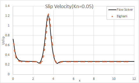
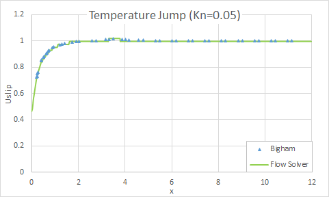
The following figures show the comparison of the flow solver results with theoretical results for the slip velocity and temperature jump results for the Kn=0.05.
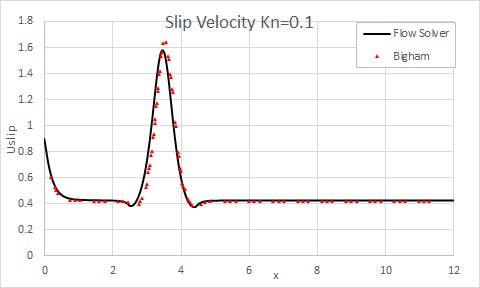
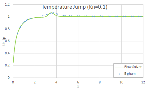
The following figures show the comparison of the flow solver results with theoretical results for the slip velocity and temperature jump results for the Kn=0.1.
