VVF15 - Incompressible laminar lid-driven cavity
| Test case |
|---|
| SVTEST193 |
Description
This test case examines the steady, incompressible, laminar lid-driven cavity flow. Despite its simple geometry, the lid-driven cavity flow retains a rich fluid flow structure manifested by multiple counter rotating recirculation regions near the corners of the cavity depending on the Reynolds number.
Geometry
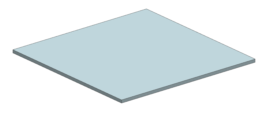
The geometry is an extruded square: 100 mm (+ X-dir) x 100 mm (+ Y-dir) x 2 mm (+Z-dir).

Simulation Model
This model uses the Advanced Thermal-Flow solution type.
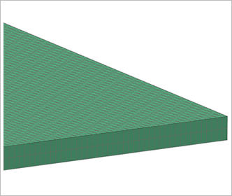
The swept mesh is made of hexahedral elements. The following mesh controls are used without any bias:
- 200 elements along the + Y-dir
- 200 elements along the + X-dir
- 2 elements along the + Z-dir
Total number of elements: 80,000
Total number of nodes: 121,203

The fluid is modeled using incompressible air with the following properties:
- Mass density: ρ = 1.21 kg/m3
- Thermal conductivity: k = 1 W/mm·C
- Dynamics viscosity: µ = 1.85 x 10⁻⁵ Pa·s
- Specific heat at constant pressure: Cp = 1 J/kg·K
The gas constant is kept blank in order to simulate a truly incompressible flow.
The following boundary conditions are applied:
- Symmetry Plane on the +Z and −Z walls
- Flow Surface: Boundary Flow Surface on the +X, −X and −Y walls using No Slip Wall conditions
- Flow Surface: Boundary Flow Surface on the + Y wall with specified velocity Ulid = 15.29 mm/s
The following solution option is set:
- Turbulence Model: None (Laminar Flow)
The following solver parameters are selected:
- 3D Flow Solver: Maximum Residuals = 1e-6
- Advection Schemes Momentum : Second-order (CDS)
- Limiter : Automatic; Momentum Limiter Stabilization : General Convective Boundedness Condition
Theory
The laminar incompressible flow in a square cavity whose top wall moves with a uniform velocity in its own plane has served extensively as a model problem for testing and evaluating numerical techniques. The multiple recirculation regions in the vicinity of the corners of the cavity provides for interesting flow features to test and benchmark numerical methods.
Results
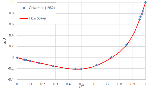
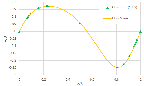
The following section presents the results of a dimensionalized u-velocity and v-velocity profiles as a function of respectively the y and x centerline of the fluid domain.
Steady-state centerline u-velocity at Re = 100:

Steady-state centerline v-velocity at Re = 100:

The figures above compare the theoretical data with computed data. A grid size of 200x200x2 was selected yielding a maximum percent difference of 0.69% in streamwise direction and 0.37% in the crosswise direction with the steady state results of Ghia et al.[18].
