VVF7 - Incompressible turbulent flow in a circular pipe
| Solution | Test case |
|---|---|
| Standard K-Epsilon | SVTEST167 |
| K-Omega | SVTEST168 |
| SST-Shear Stress Transport | SVTEST169 |
Description
This validation case examines incompressible turbulent flow in a circular pipe using the k-ε, k-ω and Share Stress Transport (SST) turbulence models. In this case, the flow enters the pipe with a constant velocity profile and develops into a logarithmic profile in the entrance region.
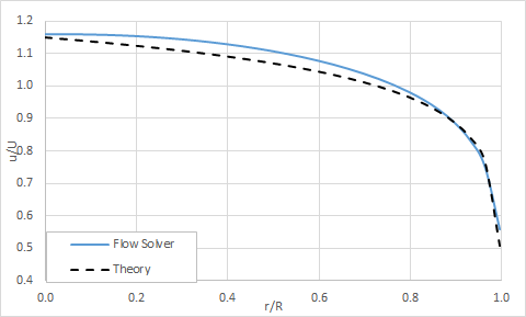
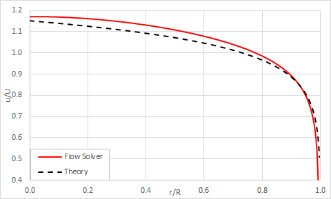
- The fully-developed velocity profile at the end of the pipe computed by the flow solver is compared to Karman-Prandtl semi-empirical logarithmic law.
- The skin friction coefficient at the end of the pipe computed by the flow solver is compared to Haaland’s explicit formula of Moody’s chart for turbulent flow.
Geometry
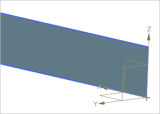
The geometry consists of a rectangle of 2000 mm in length and 10 mm in height, which is made of bounded plane from XZ plane. The following figure shows the geometry and its position relative to the global coordinate system.
The same geometry is used for all three turbulence models.
Simulation model
This model uses the Advanced Flow solution type.
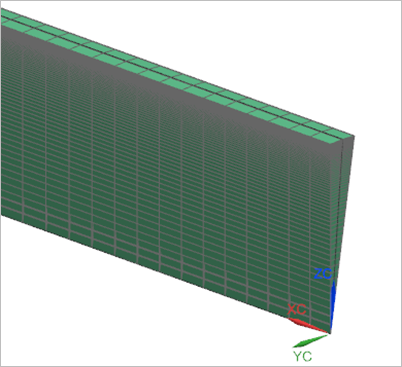
For the k-ε turbulence model, the mapped mesh of quadrilateral elements is used for X-Z lower surface of the prism. The following mesh controls are used on the surface of the rectangle:
- Height: 30 elements, 1.0 bias
- Length: 300 elements, 1.009 bias
For the k-ω and SST turbulence models, mapped mesh of quadrilateral elements is used for X-Z surface of the prism. The following mesh controls are used on the surface of the prism:
- Height: 100 elements, 1.0644 bias
- Length: 300 elements, 1.009 bias
The revolved mesh is used to create the arc pipe using hexahedral elements. The following mesh controls are used:
- Number of copies: 2
- Axis of revolution: X axis
- Angle: 5° per copy
The fluid is modeled using water with the following properties:
- Mass density: ρ = 1000 kg/m3
- Thermal conductivity: k = 0.6033 W/m·C
- Dynamic viscosity: µ = 1.006e-003 Pa·s
- Specific heat at constant pressure: Cp = 4182 J/kg·K
The following boundary conditions are used for all of the turbulence models:
- Flow Boundary Condition: Inlet Flow on the front of the arc pipe with a velocity of 5 m/s.
- Flow Boundary Condition: Opening on the back of the aft section of the arc pipe.
- Periodic Boundary Condition: Rotational Periodicity on the radial walls of the arc pipe.
For the k-ε model, the following is used:
- Flow Surface: Boundary Flow Surface on the outer surface of the arc pipe using No Slip Wall condition with smooth wall friction. Wall functions are turned on.
For the k-ω and SST models, the following is used:
- Flow Surface: Boundary Flow Surface on the outer surface of the arc pipe using No Slip Wall condition with smooth wall friction. Wall functions are turned off.
The following non-default solver options are used for all turbulence models:
- Turbulence model: The corresponding turbulence model is used (K-Epsilon, K-Omega, Shear Stress Transport-SST).
- Initial conditions: Uniform with the intensity of 0.01 and eddy length of 1.4 mm set in the Turbulence Characteristics modeling object.
The following non-default solver parameters are used for all the turbulence models:
- 3D Flow Solver: Physical steady-state with time step = 0.004 s
- 3D Flow Solver: RMS residuals = 1e-6
- 3D Flow Solver: Iteration limit = 10000
- Global Relaxation Factor: 0.3
- Mass Relaxation Factor: 0.2
- Fluids Relaxation Factor: 0.2
Theory
For a surface that is nearly hydrodynamically smooth, the velocity distribution is given by the Karman-Prandtl [32] semi-empirical logarithmic law:
where:
- u the axial velocity component.
- y is the radial distance.
- u* is the shear velocity.
The shear velocity is defined as [33] :
Haaland’s explicit formula [34] of Moody’s chart for turbulent pipe flow is used to compute the wall shear stress at the end of the pipe:
where:
- Red is the Reynolds number based on the pipe’s diameter.
- d is the pipe’s diameter.
- e is the roughness height.
For a hydrodynamically smooth surface, e = 0. f is the friction factor, defined as:
where:
- τw is the wall shear stress.
- ρ is the water density.
- Uref is the inlet velocity.
The skin friction coefficient is then computed using the following definition:
Results
The following figures represent results for the turbulence model`s velocity profile at the end of the pipe:
k-ε
k-ω
Share Stress Transport (SST)
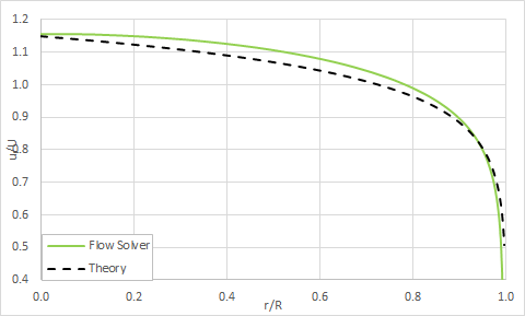
The following figure compares the solution for all three turbulence models:
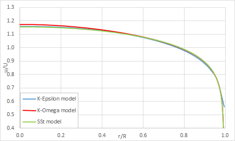
The following table compares the fully-developed skin friction coefficient predicted by all turbulence models.
| Parameter | Cf | Error (%) |
|---|---|---|
| Theory | 0.004462 | - |
| k-ε | 0.004574 | 2.52 |
| k-ω | 0.004378 | 1.89 |
| SST | 0.004435 | 0.59 |
