VVF11 - Compressible flow in a converging diverging nozzle
| Flow boundary conditions | Test case |
|---|---|
| Case1 | SVTEST180 |
| Case2 | SVTEST181 |
| Case3 | SVTEST182 |
| Case4 | SVTEST183 |
Description
This case examines the compressible flow in a converging diverging nozzle. The flow is simulated by imposing a pressure difference between the nozzle inlet and exit. This case investigates two subsonic and two transonic cases.
Geometry
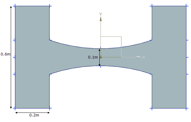
The nozzle is 0.6 m in length, the ends are 0.2 m wide and the throat is 0.1 m wide.

Simulation model
This model uses the Advanced Flow solution type.
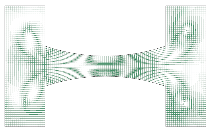
The X-Y face of the model is meshed using 2D quadrilateral elements that are 10 mm element size and are paved onto the X-Y face. The swept mesh is made of hexahedral elements with 4 mm in size.

The fluid is modeled using compressible air with the following properties:
- Mass density: ρ = 1.2041 kg/m3
- Thermal conductivity: k = 0.0263 W/(m·K)
- Thermal expansion coefficient: β = 3.41 × 10⁻³ K−1
- Specific heat at constant pressure: Cp = 1007 J/(kg·K)
- Gas constant: R = 287 J/(kg·K)
- Dynamic viscosity: µ = 1.85 × 10⁻⁵ kg/(m·s)
The following boundary conditions are applied:
- Flow Surface: Boundary Flow Surface on the 6 planes bounding the nozzle portion using a Slip Wall.
- Symmetry Plane on the two surfaces in parallel with X-Y plane.
-
Flow Boundary Condition: Opening on the three surfaces of the inlet and on the three surfaces of the outlet with a pressure at the outlet vent provided in the following table.
Case Inlet pressure (MPa) Outlet pressure (MPa) 1 0.1 0.08 2 0.1 0.085 3 0.1 0.0925 4 0.1 0.095
The following solution options are set:
- Turbulence Model: K-Epsilon
- Solution Type: Steady State
- Ambient Conditions: Fluid temperature = 20 ºC, absolute pressure value = 0.1 MPa
- 3D Flow: Slip Wall, High Speed Flow is selected
The following solver parameters are set:
- Thermal Solver: Iteration limit 10000
- 3D Flow Solver: Physical steady-state with time step = 0.001 s
- 3D Flow Solver: Maximum Residuals = 1e-06
- 3D Flow Solver: Iteration limit =10000
Theory
Compressible flow through a converging-diverging nozzle is a classic fluid mechanics problem. For the ideal flow the Mach number is defined as:
where:
- M is the Mach number.
- v is the object speed.
- a is the sound speed.
Sound speed is computed as:
where γ = 1.4.
The first relation governing the flow in a nozzle is:
The relation between the pressure and temperature has to be satisfied between every two points of the stream and not separated by a normal shock. The sonic velocity can be attained only at the throat.
The relation between pressure and Mach number on each side of a normal shock is given by:
Results
The following table shows the pressure ratio comparison between the inlet and throat using temperature.
| Inlet | Throat | Results | |||||
|---|---|---|---|---|---|---|---|
| Pout/Pin | Abs P1 (MPa) | T1 (K) | Abs P2 (MPa) | T2 (K) | Simulation | Theory | Difference (%) |
| Abs P2/P1 | P2/P1 | ||||||
| 0.8 | 0.0995 | 292.8 | 0.0527 | 244.8 | 0.5303 | 0.535 | 0.83 |
| 0.85 | 0.0995 | 292.8 | 0.0528 | 244.9 | 0.5313 | 0.536 | 0.85 |
| 0.925 | 0.0996 | 292.8 | 0.0706 | 266.6 | 0.7093 | 0.720 | 1.55 |
| 0.95 | 0.0997 | 292.9 | 0.0821 | 277.9 | 0.823 | 0.831 | 1.01 |
The following table shows the pressure ratio comparison between the inlet and throat using a Mach number.
| Inlet | Throat | Results | ||||
|---|---|---|---|---|---|---|
| Pout/Pin | Abs P1 (MPa) | P2 (MPa) | Mach 2 | Simulation | Theory | Difference (%) |
| Abs P2/P1 | P2/P1 | |||||
| 0.8 | 0.0995 | 0.0527 | 0.995 | 0.530 | 0.531 | 0.18 |
| 0.85 | 0.0995 | 0.0529 | 0.995 | 0.532 | 0.531 | -0.01 |
| 0.925 | 0.0996 | 0.0706 | 0.706 | 0.709 | 0.717 | 1.08 |
| 0.95 | 0.0997 | 0.0821 | 0.525 | 0.822 | 0.829 | 0.69 |
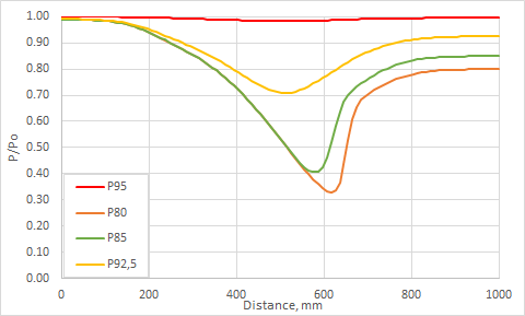
The following figure compares the pressure ratio along the nozzle for various outlet pressures.

