VVF19 - Isentropic compressible flow in a converging diverging nozzle
| Mesh | Flow boundary conditions | Test case |
|---|---|---|
| Coarse | Weak shock | SVTEST197 |
| Strong shock | SVTEST198 | |
| Fine | Weak shock | SVTEST199 |
| Strong shock | SVTEST200 |
Description
This test case examines the isentropic compressible flow in a converging diverging nozzle. Two supersonic cases are investigated for coarse and fine meshes: one with a weak shock and another with a strong shock. Both shocks are located in the diverging section of the nozzle. The objective of these simulations is to predict the normal shock location as well as flow properties before and after the shock. The location, Mach number, temperature, and pressure of the shock are compared to the 1D analytical results.
Geometry
The nozzle is 0.6 m in length, the ends are 0.2 m wide and the throat is 0.1 m wide. The flow is simulated by imposing a pressure difference between the inlet and exit. The following figure identifies the points defined in a sketch that generate the basic geometry of the model.

Simulation model
This model uses the Advanced Flow solution type.
The mesh characteristics are identified in the following figure.

A 2D seed mesh is created using quadrilateral elements. The values used for this mesh is summarized in the following table.
| Mesh | Blue | Red | Yellow |
|---|---|---|---|
| Coarse | 62 | 40 | 20 |
| Fine | 124 | 80 | 20 |
The 2D mesh is swept through the thickness of the nozzle to create 4 mm hexahedral elements.
The fluid is modeled using incompressible air with the following properties:
- Mass density: ρ = 1.204 kg/m3
- Thermal conductivity: k = 0.0263 W/m·K
- Dynamic viscosity: µ = 1.85e-005 kg/m·s
- Specific heat at constant pressure: Cp = 1007 J/kg·K
- Coefficient of thermal expansion: β = 0.00341 1/°C
- Gas constant: R = 287 J/kg·K
The following boundary conditions are applied:
- Flow Boundary Condition: Inlet Flow on the one side of the nozzle with ambient pressure and a temperature of 300 K.
- Flow Boundary Condition: Outlet Flow on the opposite side of the nozzle.
The values of the absolute pressures used for the weak shock and strong shock cases are summarized in the following table.
| Case | Inlet total pressure (Pa) | Outlet static pressure (Pa) |
|---|---|---|
| Weak shock | 100,000 | 90,000 |
| Strong shock | 100,000 | 55,000 |
- Report: Per Region on the inlet of the nozzle with selected velocity and pressure 3D flow data.
- Report: Per Region on the throat of the nozzle with selected temperature, velocity and pressure 3D flow data.
The following solution options are set:
- Turbulence Model:None (Laminar Flow)
- Solution Type:Steady State
- 3D Flow: select Slip Wall and High Speed Flow
- Results Options: 3D Flow select the Velocities Adjusted, Fluid Densities, Surface Pressures, and Mach Numbers
The following solver parameters are selected:
- 3D Flow Solver: Time Step: 0.001
- 3D Flow Solver: Maximum Residuals = 1e-08
Theory
The analytical solution for the isentropic 1D flow in a converging diverging nozzle can be obtained using:
- The isentropic relations from the inlet to the location of the shock.
- The normal shock relations to determine the discontinuous properties across the shock.
- The isentropic relations to evaluate the properties downstream of the shock.
The Mach number is defined as:
where:
- v is the speed of the air.
- c is the speed of sound.
The sound speed is computed as:
where:
- γ is the specific heat ratio equal to 1.4 for air.
- R is the gas constant.
- T is the absolute temperature of the air.
The isentropic relations are the following [21]:
where the subscript T denotes a total pressure, density, or temperature and A* is the area at the thought of the nozzle. An online applet for calculating these relations was created by NASA [51].
The normal strong shocks relations are the following:
where, the subscript x denotes a property that is upstream of the shock and the subscript y denotes a property that is downstream of the shock.
In order to solve for properties at a particular location within the nozzle, you must iterate the location of the shock until the above mentioned relations are non-contradicting [52].
Results
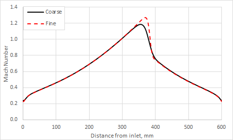
The following figure presents the Mach numbers obtained for the weak shock cases.

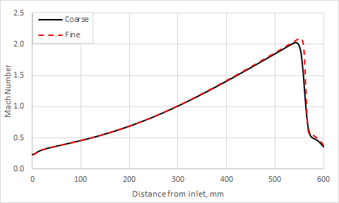
The following figure presents the Mach numbers obtained for the strong shock cases.

The Mach number, static pressure, temperature ratios, and the ratio of shock to thought area are listed for the weak and strong shock cases in the following table.
| Parameter | Weak shock | Strong shock | ||||||
|---|---|---|---|---|---|---|---|---|
| Mesh | My/Mx | Py/Px | Ty/Tx | Ax/A* | My/Mx | Py/Px | Ty/Tx | Ax/A* |
| Coarse | 0.65 | 1.56 | 1.13 | 1.03 | 0.30 | 3.81 | 1.61 | 1.73 |
| Fine | 0.62 | 1.67 | 1.16 | 1.05 | 0.28 | 4.04 | 1.66 | 1.79 |
| Quasi-2D analytical solution | 0.55 | 2.02 | 1.23 | 1.10 | 0.26 | 5.15 | 1.80 | 1.89 |
The discrepancies between the two solutions come from the use of a pressure-based solver, for which the accuracy and robustness suffer from limitations, to predict fully compressible flow.
