VVF13 - Low pressure slip wall boundary conditions
| Gas density | Test case |
|---|---|
| Constant | SVTEST188 |
| Variable | SVTEST189 |
Description
This validation case examines the slip wall boundary conditions at low pressure Poiseuille channel flow for constant and variable gas densities. At low absolute pressures the Knudsen number becomes large and the slip wall boundary should be applied. In the situations where the no-slip assumption is no longer valid, the velocity of the gas next to the wall have to be adapted. The idea is to relax the traditional no-slip boundary condition to allow the rarefied gas to slip at the wall by imposing a tangential component of the slip velocity at the solid boundary. This case compares the first-order and second-order velocity derivative terms with theoretical results.
Geometry
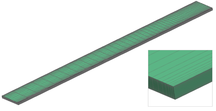
The geometry consists of a parallel plate channel with a height (H) of 0.1 m. The validation model is shown in the following figure.

Simulation model
This model uses the Advanced Flow solution type.
The swept mesh is made of hexahedral elements with the following mesh controls defined:
- Height: 20 elements, 1.25 bias, center of edge
- Length: 50 elements, 1.05 bias, end of edge
The fluid is modeled using air with the following properties:
- Mass density: ρ = 1.2041 kg/m3
- Thermal conductivity: k = 0.0263 W/m·C
- Dynamic viscosity: µ = 1.85e-05 Pa·s
- Specific heat at constant pressure: Cp = 1007 J/kg·K
- Gas constant: R = 287 J/kg·K
The following boundary conditions are applied:
- Flow Boundary Condition: Inlet Flow on the one end of the channel with a velocity of 1 m/s and a temperature of 1000 K
- Flow Boundary Condition: Opening on the opposite end of the channel with an absolute pressure of 10 Pa
- Symmetry Plane on the two side faces
- Flow surface: Boundary Flow Surface on the top and bottom faces using a Slip Wall
The following solution options are used:
- Turbulence Model: None (Laminar Flow)
- Solution Type: Steady State
- Initial Conditions: Temperature = 1000 K, absolute pressure = 10 Pa
The following advanced parameters are selected:
-
USE LOW-PRESSURE MAXWELL SLIP WALL TREATMENT -
MAXWELL SLIP WALL C2: - 0.5 -
OUTPUT LOW-PRESSURE MAXWELL SLIP WALL SUMMARY -
REFERENCE TEMPERATURE FOR SLIP CORRECTION: 291.15 K -
REFERENCE PRESSURE FOR SLIP CORRECTION: 101350 Pa -
REFERENCE VISCOSITY FOR SLIP CORRECTION: 1.827e-005 Pa·s -
SUTHERLAND CONSTANT FOR SLIP CORRECTION: 120
In addition, the following advanced parameters are added through the user.prm file:
-
GRADIENT_BOUNDARY_TREATMENT_VEL: 1 -
GRADIENT_BOUNDARY_TREATMENT_PRESS: 1 -
USE_NODAL_MAXWELL_SLIP_VALS = TRUE -
MEAN_FREE_PATH_LAMBDA: 0.002919 -
LOW_PRESSURE_SLIP_WALL_CV: 720.0
The first three parameters activate the nodal wall treatment for velocity and pressure. The last two parameters treat the gas with a constant density and a fixed value for the mean free path of the gas.
The following solver parameters are set:
- 3D Flow Solver: Physical steady-state time step: 0.1 s
- 3D Flow Solver: Maximum Residuals = 1e-6
- 3D Flow Solver: Steady state iteration limit = 1000
Theory
Assuming a constant density and mean free path for the gas, the analytical solution to this model is shown in the following equation:
where:
- U is the x component of velocity.
- Ui is the inlet velocity.
- Y* is the non-dimension wall-normal distance equal to y/H.
- y is the distance from bottom wall.
- H is the channel height.
- C1 is the first order slip coefficient.
- C2 is the second order slip coefficient.
- Kn is the Knudsen number equal to λ/H.
- λ is the free mean path of the gas.
Results
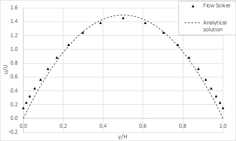
The following shows the analytical and flow solver results for the velocity profile in the channel with variable densities.

Errors for the solver results are less than 2% when compared to the analytical solution. These errors can be attributed to the fact that the analytical solution assumes a constant density for the gas, whereas the solver calculates the density at every element using the ideal gas equation and the local pressure and temperature. Furthermore, the solver uses this information to update the mean free path of the gas at every wall element, instead of using a constant value as it is assumed by the analytical solution.
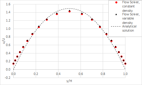
The following shows the resulting analytical and solver results for the velocity profile in the channel with constant density. In this case the errors are less than 1%.

