Radiation modeling for cyclic symmetric models with rotational periodicity
This article explains how to model radiation heat transfer in cyclic symmetric thermal models. It also provides practical recommendations to balance accuracy and computational efficiency, since radiation calculations are often computationally expensive.
Why use cyclic symmetry?
For turbomachinery applications, where blades or vanes repeat around a global axis of revolution, modeling a representative sector (typically 5°–30°) can significantly reduce simulation time and memory requirements. When cyclic symmetry is correctly defined, the thermal solver accounts for the full 360° geometry by scaling conduction, convection, and radiation effects appropriately.
However, radiation modeling in complex cyclic symmetric geometries requires special attention to ensure that heat exchange is represented correctly, as the choice of radiative rotational periodicity affects whether radiation is scaled within a sector or computed across the full 360° geometry.
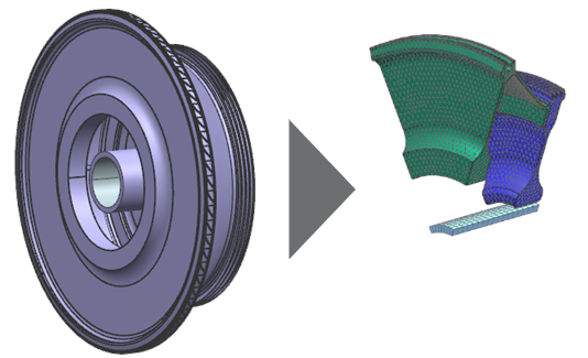
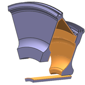
The model in this example is a 3D cyclic symmetric sector of the full model of the High-Pressure Compressor (HPC) disk, lab seal disk, and shaft.
Modeling cyclic symmetric components
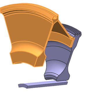
The Cyclic Symmetry simulation object allows you to model a rotationally periodic structure using only a representative sector. Define a separate Cyclic Symmetry object for each component, for example, disk, seal, and shaft.
Do not use a single Cyclic Symmetry object for multiple components when interferences or contacts exist. Doing so can introduce unintended thermal couplings between unrelated parts. You can use temperature plots to visually validate that components are properly decoupled.
Define the source (1) and the target (2) regions for each component. If the message The angle must be between 0 and 180 degrees appears while defining the cyclic sector, swap (3) the source and target selections to resolve the issue.
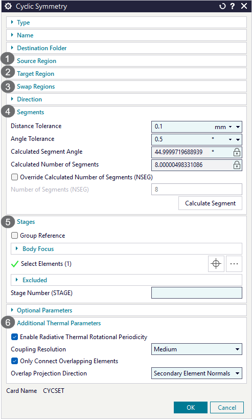
- Defining the number of cyclic segments (4)
- In some cases, the software cannot automatically determine the number of
cyclic sectors. This issue can occur due to:
- Twisted or misaligned cut geometry.
- Improper distance or angle tolerances.
- Non-periodic geometry.
To fix this issue:
- Increase the Distance Tolerance up to 1 mm, if necessary.
- Adjust the Angle Tolerance.
- Verify geometric periodicity using measurement tools. Confirm that arcs are centered on the axis of rotation and that the geometry is radially consistent.
- Realign the geometry or divide it into smaller sectors.
In this model example, the software has detected 8 cyclic segments as expected.
- Selecting elements in the stages (5)
- In the stage group, it is important to select 3D sector of the component.
When modeling conduction, convection, and radiation in cyclic symmetric parts, the thermal solver does not explicitly expand the modeled sector into a full 360° geometry. Instead, it scales thermal quantities to represent the full model. The thermal solver uses the axis of revolution, the coupling resolution, and specified overlap settings. For example, if you define thermal coupling between a sector face and another component, the coupling only occurs within the sector. However, the solver scales the thermal capacity and coupling area to reflect the full 3D geometry.
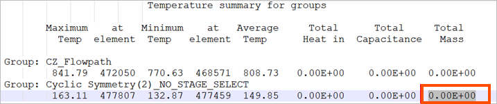
When you do not select all elements or bodies of the cyclic sector in the Stages group of the Cyclic Symmetry simulation object, the solver incorrectly scales surface areas, thermal conductivity, and specific heat. The simulation may still produce periodic temperatures, but physical quantities such as mass, capacitance, and energy totals become invalid. For example, the output data summary table may show a total mass of zero when no stage elements are selected.
 Note:
Note:In some cases, you should not define elements in the stage. Do not apply stage scaling if your applied inputs are already consistent with the visible mesh section. For example, if thermal quantities are defined per blade rather than for the entire engine, you should not include stage elements. Applying stage scaling in this case would incorrectly multiply the flow.
- Defining additional thermal parameters (6)
- To choose the appropriate radiation rotational periodicity modeling
approach, it is important to understand how the thermal solver computes
radiative heat transfer in cyclic symmetry.
When the Enable Radiative Thermal Rotational Periodicity check box is cleared:
- View factors are computed once for the modeled sector.
- Radiative conductances are scaled based on the number of cyclic segments.
Use this approach when:
- Radiating surfaces exchange heat only within the same sector.
- Cross-sector radiation is not physically significant.
When the Enable Radiative Thermal Rotational Periodicity is enabled for the entire model:
- The solver internally expands the 3D sector into a full 360° representation.
- View factors are computed to capture cross-sector radiation effects.
Use this approach when surfaces in one sector can radiate to adjacent sectors or other repeating components. This approach represents a trade-off:- Higher computational cost
- Improved physical accuracy for complex radiative interactions
Modeling enclosure radiation
The Enclosure Radiation type of the Radiation simulation object allows you to model radiation exchange between the faces in the cavity.
To improve radiation calculation performance in cyclic symmetrical models, it is recommended to use the GPU Computed View Factor calculation method. The thermal solver computes radiative view factors on the GPU, based on the modified Monte Carlo ray tracing method. This method supports diffuse emissivity and diffuse reflectivity thermo-optical properties. The GPU view factor calculation is much faster than the GPU computed ray tracing method.
Defining thermal solution parameters for radiation
To speed up the solve when radiation is included, you can adjust view factor calculation (1) and use radiation patches (2).
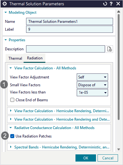
- Adjusting view factor calculation (1)
- You can increase the default cutoff value to dispose view factors smaller than this threshold. For turbomachinery applications, it is recommended to use 1e-05. When you change this value, you must perform a sensitivity study.
- Using radiation patches (2)
- When the Use Radiation Patches check box is selected on the radiation parameters page, adjacent Oppenheim elements are temporarily merged into separate patches during the radiative exchange calculation. When you use this option, the number of view factors remains unchanged, and the number of radiative conductances is reduced.