Thermal coupling in models containing internal lines
This topic explains how to model thermal coupling in axisymmetric models with internal lines.
This lesson may include hands-on exercises. Review the Discussion section for background information or click the button to proceed to the practical section.
Discussion
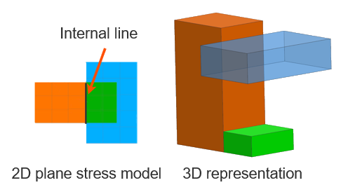
An internal line in an axisymmetric model is a shared edge between two adjacent regions that represents a physical interface between components in 3D. Although it appears as a line in 2D, it represents a finite contact surface area in 3D:
In the following example:
- The orange and green regions share an internal line (common nodes), representing a direct interface.
- The blue region does not share an internal line but is thermally coupled to the orange region.
The effective thermal coupling area depends on:
- The primary selection used to define the coupling.
- The Only Connect Overlapping Elements option, which controls how the interface is evaluated.
The following table illustrates how the thermal coupling area is calculated in models with internal lines, depending on whether overlapping elements are considered.
| Primary selection | Only Connect Overlapping Elements = OFF | Only Connect Overlapping Elements = ON |
|---|---|---|
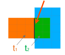 |
||
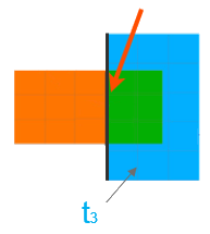 |
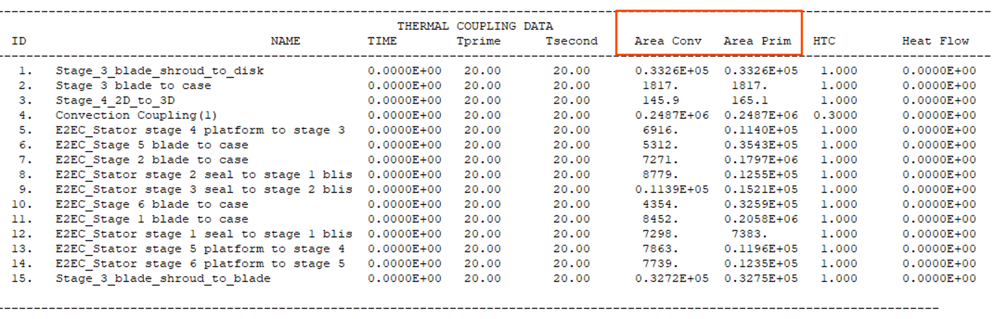
- Verifying the primary and convective areas
- To check the area at solve time, include the DISPLAY BC SUMMARY
TABLES advanced parameter in the solution. The thermal
solver generates the <simulation name>-<solution
name>.bcdata file, which includes primary and convective
areas for the thermal couplings. This file is updated at each successful
time step during the solve and stored in the run or scratch directory.
Hands-on material
To gain experience with the topics discussed here, complete the following: