Modeling considerations for embedded edges
This topic explains how to model thermal contacts with embedded edges.
This lesson may include hands-on exercises. Review the Discussion section for background information or click the button to proceed to the practical section.
Discussion
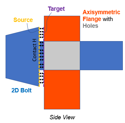
When modeling thermal contact interfaces with embedded edges, such as bolts in flanges, you must carefully define source and target regions to ensure accurate heat transfer and contact behavior.
Select the bolt head edge as the source and the flange edge as the target. This setup must remain consistent with the CAD and FEM representations to correctly capture the physical interface.
To ensure accuracy:
- Divide bolt faces at intersections with the flange.
- Define separate meshes and thickness values for the bolt head and bolt shank.
Although this example focuses on bolts, the same approach applies to other embedded-edge interfaces such as scallops or anti-rotation features.
Hands-on material
To gain experience with the topics discussed here, complete the following: