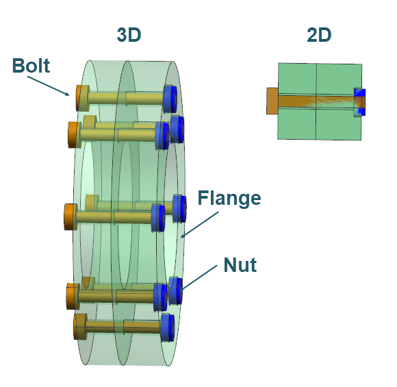
Model thermal connections of bolts, nuts, holes, and flanges
Create and compare the results of bolts, nuts, holes, and flanges thermal connections between the 3D model and its 2D axisymmetric representation. You will model the flange as an axisymmetric part using axisymmetric elements because it is revolved around the axis of rotation. You will model the nut and bolt as repeated cyclic symmetric parts around the axis of rotation using plane stress elements.
Open the Simulation file
Open the Simulation file and reset the dialog box settings to ensure that they are in the expected initial state.
-
Click OK.
The model consists of two parts:
- The 3D model of two flanges fastened together by 8 bolts and nuts.
- The 2D axisymmetric representation of the 3D model.
Stitch free edges in a 2D model
Inspect and stitch free edges for a 2D model within solid bodies of bolts, and flanges to correctly model heat conduction through the bodies.
-
Click OK.
The free edges are displayed in the graphics window. Notice, for example, that the flange bodies have free edges and are not connected. You must connect geometrically disconnected parts to model heat conduction through the bodies. You can thermally connect the bodies by stitching the edges or creating thermal coupling between them. In this example, you will stitch free edges between flanges.
-
Choose Home tab→Polygon
Geometry group→Stitch Edge
 .
.
-
Click Apply.
Mesh the flange with axisymmetric elements
Create a mesh collector and define the mesh for two flanges using axisymmetric elements since the geometry of flanges is a solid of revolution.
-
Choose Home tab→Mesh
group→2D Mesh
 .
.
-
In the graphics window, select the four faces of two flanges.
- From the Type list, select Axisymmetric Linear Quadrilateral.
- In the Element Size box, type 0.5.
-
In the Destination Collector group, click
New Collector
 .
.
- In the Physical Properties sub-group, from the Solid Property list, select Solid 1, which is the predefined solid with the AISI_310_SS material.
- In the Name box, type AXI.
- Click OK to close both dialog boxes.
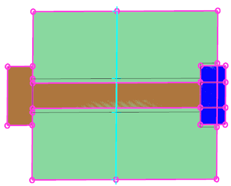
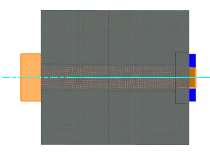
Mesh the hole with plane stress elements
Create a mesh collector and define the mesh for two flanges using axisymmetric elements since the geometry of flanges is a solid of revolution.
-
Choose Home tab→Mesh
group→2D Mesh
.
-
In the graphics window, select the three faces as shown in this example.
When you solve the model, the solver subtracts the material in the hole's
plane stress mesh from the material for the remainder of the model.
-
In the Exclude Edges Transverse to Centerline
sub-group, click Select Edge and select the two
highlighted edges to exclude them from the thickness calculations.
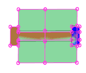
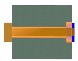
Mesh the bolt with plane stress elements
Create a mesh collector and define the mesh for bolts in the flanges.
-
Choose Home tab→Mesh
group→2D Mesh
.
-
In the graphics window, select three faces of the bolt geometry.
Tip: To facilitate the selection of the bolt face, deselect the nut polygon geometry.
-
In the Exclude Transverse to Centerline sub-group,
click Select Edge and select the two highlighted
edges to exclude them from the thickness calculations.
-
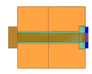
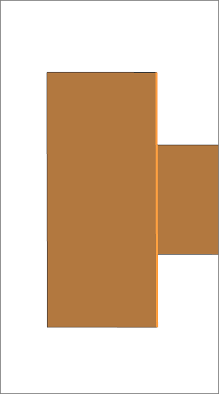
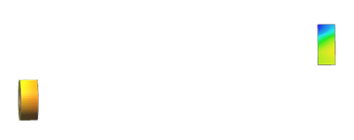
In the Simulation Navigator, right-click
PS_BOLTS and choose Plot Thickness
Contour to verify if the bolt thickness is correctly
defined.
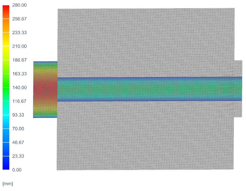
Note that the thickness is zero on the edges of the bolt, and the highest thickness is 280 mm in the centerline of the bolt head. -
Choose Home tab→Context
group→Return to Model
 .
.
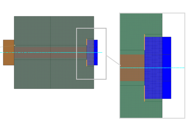
Mesh the nut with plane stress element and define its thickness
Create a mesh collector and define mesh for nuts.
-
Choose Home tab→Mesh
group→2D Mesh
.
-
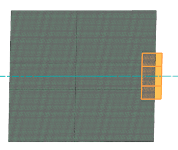
In the graphics window, select three faces of the nut geometry. To
facilitate the selection, you can deselect the
PS_BOLTS mesh collector and
Bolt geometry.
- In the Element Properties group make sure that Plane Stress Linear Quadrilateral is selected.
- In the Destination Collector group, click New Collector.
- In the Physical Properties sub-group, from the Plane Property list, select Plane Property 1.
- In the Name box, type PS_NUTS.
- Click OK to close both dialog boxes.
Determine area factor for modeling nut thickness
Since there is no predefined thickness source for the nut, you will define the nut thickness with an expression. You must determine the area factor for the 2D nut mesh so that the total nut mass is the same in 3D and 2D.
- In the Simulation Navigator, under the PS_NUTS mesh collector, click SHIFT and select nut mesh under PS_NUTS, right-click and choose Edit Mesh Associated Data.
- In the Element Properties group, in the Thickness sub-group, from the Thickness Source list, select Field/Expression.
- In the Thickness box, type 2*pi()*radius to define the thickness of the nut, disregarding the hole inside.
- In the Number of Instances box, type 8.
- Click OK.
- In the Simulation Navigator, under PS_NUTS, right-click the first nut mesh and select Solid Properties.
- In the Information window, check the total mass. It shows that the total mass is 8.24843 kg.
- Close the Information window.
- Repeat steps 6-8 for each nut mesh to verify the masses of each nut and sum them. The sum is 31.373724 kg.
- To verify the total mass in 3D model, right-click model2_fem1.fem x 8 and select Open in Window.
- In the opened window, expand 3D Collectors → Nut, right-click the nut mesh and select Solid Properties.
- In the Information window, verify that the total mass is 0.09338785 kg.
- Compute the area factor as 0.09338785/31.373724=0.002976626.
Define the correct nut mesh thickness
Explore predefined boundary conditions for 3D and 2D models
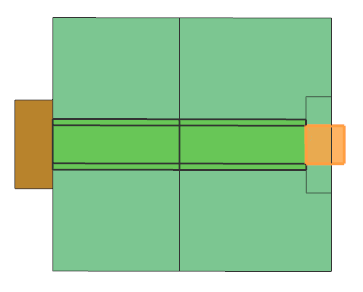
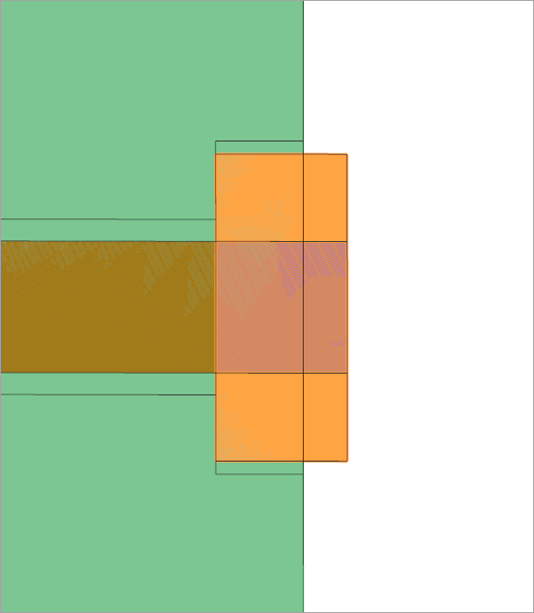
Connect the bolt and flange faces for the 2D model
Model the thermal connection between the bolt face meshed with plane stress elements, and the flange face meshed with the axisymmetric elements.
-
In the Simulation Navigator, right-click the
Simulation Object Container node and choose
New Simulation Object → Thermal
Coupling
 .
.
- Deselect all mesh collectors and under the Polygon Geometry node, display Bolt.
- In the Name group, type 2D_Bolt-Flange.
-
For the primary region, select the bolt face as it is smaller face than the
face of the flange.
-
For the secondary region, select the two flange faces that are in contact
with the bolt.
- In the Magnitude group, from the Type list, select Heat Transfer Coefficient.
- In the Coefficient box, specify 100 W/(m2·°C).
- In the Additional Parameters group, make sure that the Only Connect Overlapping Elements check box is selected to instruct the solver to connect elements in terms of proximity and an overlap check.
- Click OK.
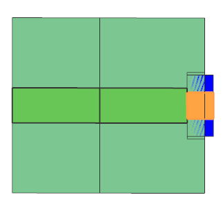
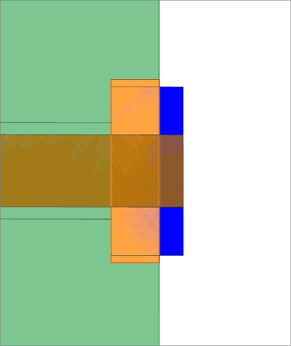
Connect the nut and bolt faces for the 2D model
Model the thermal connection between the nut face meshed with plane stress elements and the bolt face meshed with plane stress elements.
-
In the Simulation Navigator, right-click the
Simulation Object Container node and choose
New Simulation Object → Thermal
Coupling
.
-
For the primary region, select the bolt face that is in contact with the nut.
Tip: Deselect the nut geometry to select the correct bolt face.
-
For the secondary region, select the nut face that is in contact with the bolt.
Tip: Deselect the bolt geometry to select the correct nut face.
Connect the nut and flange edges for the 2D model
Model the thermal connection between the nut edge meshed with plane stress elements and the flange edge meshed with axisymmetric elements.
-
In the Simulation Navigator, right-click the
Simulation Object Container node and choose
New Simulation Object → Thermal
Coupling
.
-
For the primary region, select the three highlighted nut edges.
Tip: Use the Polygon Edge filter. For easier selection, you can display only the nut geometry.
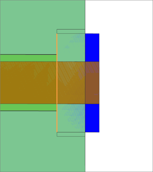
-
For the secondary region, select the three flange edges that are in contact
with the nut.
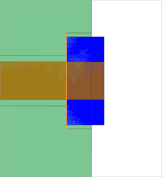
Connect the nut and flange faces for the 2D model
Model the thermal connection between the nut face meshed with plane stress elements and the flange face meshed with axisymmetric elements.
-
In the Simulation Navigator, right-click the
Simulation Object Container node and choose
New Simulation Object → Thermal
Coupling
.
-
For the primary region, select the three nut faces that are in contact with the flange.
Tip: Use filter Polygon Face. Deselect Bolt geometry if it is selected.
-
For the secondary region, select the flange face that is in contact with
the nut.
Connect the bolt head and flange edges for 2D model
Model thermal connection between the bolt edge meshed with plane stress elements and the flange edge meshed with axisymmetric elements.
-
In the Simulation Navigator, right-click the
Simulation Object Container node and choose
New Simulation Object → Thermal
Coupling
.
-
For the primary region, select three highlighted bolt head edges.
Tip: Use filter Polygon Edge. To facilitate the selection, deselect the flange geometry.
-
Deselect the bolt geometry and for the secondary region, select the three
flange edges in contact with the bolt.

Solve the model
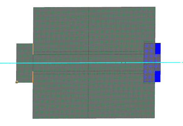
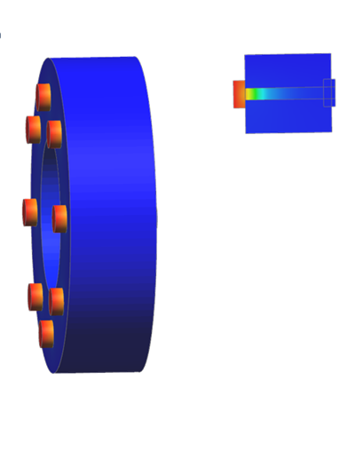
Display results
Display the temperature results.
- In the Post Processing Navigator, double-click the Thermal node to load the results.
-
Expand Thermal and double-click
Temperature - Element.
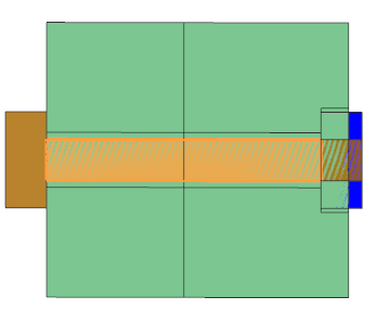
-
Expand the Post View 1 → Mesh
Collectors → assembly1_assyfem1.afm →
model3_fem1.fem node and hide
AXI, PS_HOLES,
model1_fem2.fem, 2D
Elements to compare the temperature for bolts and
nuts.
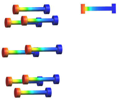
- To display nut results for 2D model, hide PS_BOLTS.
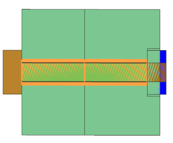
-
To display nut results for 3D model, hide all eight
model2_fem1.fem. Expand first
model2_fem1.fem and display
Nut.
Investigate thermal coupling areas in the HTML file
The model contains the DISPLAY BC SUMMARY advanced parameter. You will compare the coupling areas for 3D nut and bolt coupling with 2D nut and bolt coupling.
-
From the Select Second Thermal Coupling list, select
2D_Nut-Bolt.
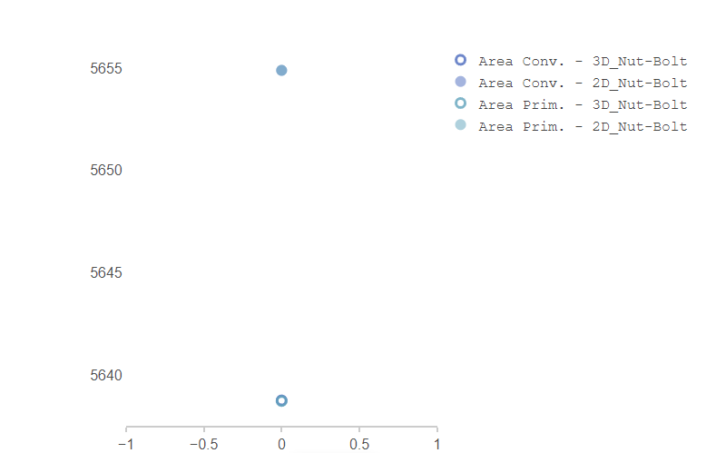
Note that convective areas are in good agreement between 3D model and 2D axisymmetric representation.