Resolve mesh quality issues
Practice the workflow for checking element quality and resolving quality problems.
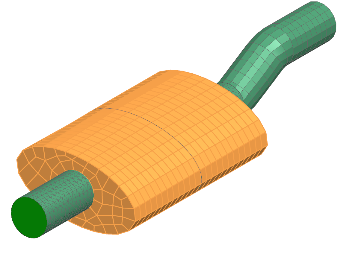
Open the FEM file
Open the FEM file and reset the dialog box settings.
- Choose File→Open and open exhaust/exhaust_fem.fem.
- Choose File→Preferences→User Interface and on the Dialog and Precision page, reset the dialog box memory.
Check for duplicate nodes
Detect and merge duplicate nodes in the displayed mesh.
-
Choose Home tab→Checks and Information group→Duplicate Nodes
 .
.
-
In the Nodes to Check group, select
Displayed.
Duplicate nodes are highlighted in the graphics window.
- Click Merge Nodes to merge a parent node to any child nodes.
- Click Close.
Check the element normal orientation
Display and adjust the normal directions of 2D elements in the mesh.
-
Choose Home tab→Checks and Information group→2D Element Normals
 .
.
-
Select the 2D mesh in the graphics window.
- Click Display Normals.
- Click Reverse Normals to make the normals point outward.
- Click Close.
Check elements quality
Run a quality check to identify and report failed and warning elements.
-
Choose Home tab→Checks and Information group→Element Quality
 .
.
- In Elements to Check, select Displayed.
- In the Output Settings group, from the Report list, choose Failed and Warning
-
Click Check Elements.
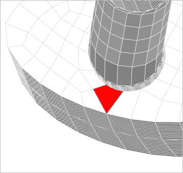
The software displays a list of failed and warning elements in a log file. In the graphics window, the failed elements are displayed in red, and the warning elements are displayed in yellow.
- Examine the report.
- Close the Log File and the Element Quality dialog box.
- Double-click the graphics window to refresh the display.
Set up a persistent element display
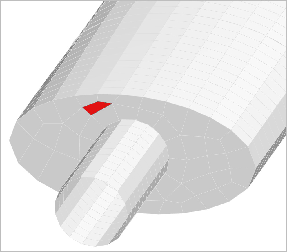
Enable display of element quality results directly in the model view.
- Choose Home tab→Tools group→Model Display Preferences.
- On the Model Colors page, set Color Basis to Element Quality Checks.
-
Click OK. Failed elements appear in red; valid elements in gray.
In the graphics window, the failed elements are displayed in red, and valid elements in gray.
Repair the failed elements
Manually fix poor-quality elements using element splitting tools.
-
Choose Nodes and Elements tab→Elements group→Split Shell
 .
.
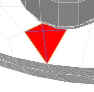
- In Split Methods, select Quad to 2 Triangles.
-
In the graphics window, select the failed element.
-
Click Flip Split Line if necessary.
The element should be split as shown.
- Click Apply.
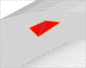
- In Split Methods, select Quad to 4 Triangles.
-
Rotate the model and select the failed element, as shown.
-
Click OK to finish splitting.