Introducing the user interface
This topic covers the user interface (UI) in Simcenter 3D Space Systems Thermal. You will learn how to navigate the modeling environment and how to efficiently use the available tools, menus, and commands to build, set up, and review your models.
This lesson may include hands-on exercises. Review the Discussion section for background information or click the button to proceed to the practical section.
Discussion
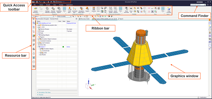
Simcenter 3D supports several workflows, including the Pre/Post application, where all preprocessing and postprocessing tasks are performed. The UI is designed to provide quick access to commonly used commands while maximizing the available graphics window area.
- User interface components
- The Simcenter 3D UI is composed of several key elements that provide efficient access to commands and support model interaction, including:
- Ribbon bar, which organizes commands in each application into tabs and groups.
- Quick Access toolbar, which contains commonly used commands such as Save and Undo.
- Resource bar, which contains tabs for navigators, a browser, and palettes.
- Graphics window, where you interact with and visualize the model.
- Command finder, which allows you to locate and activate commands using keywords.
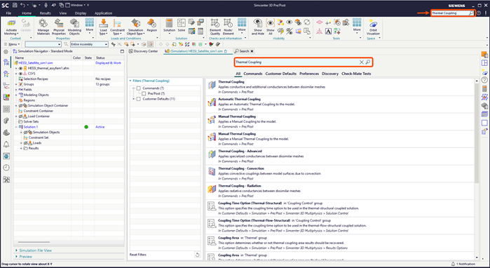
- Finding and using commands
- Use the Command finder to search for and activate commands, including commands that are not currently active in the selected application or task.
 Dialog boxes are organized in a top-down workflow to guide you through command options and confirmations.
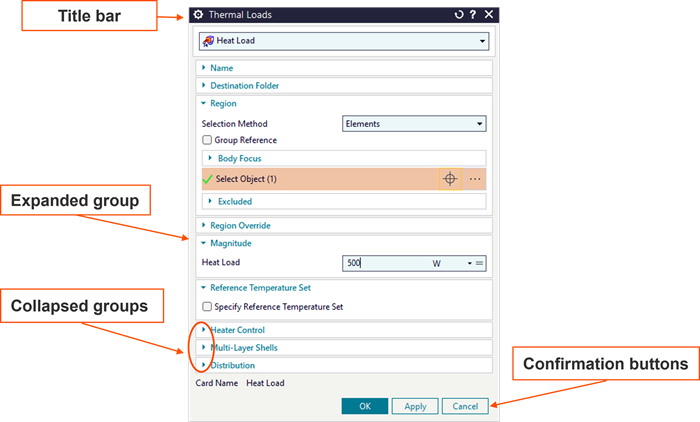
- Simulation and post-processing navigation
- The Simulation Navigator is used to perform most tasks in the analysis workflow, such as defining FEMs, meshes, boundary conditions, solutions, and results.
 The Post Processing Navigator is used to generate contour, deformation, and animated plots, manage result views, apply display templates, and annotate results.
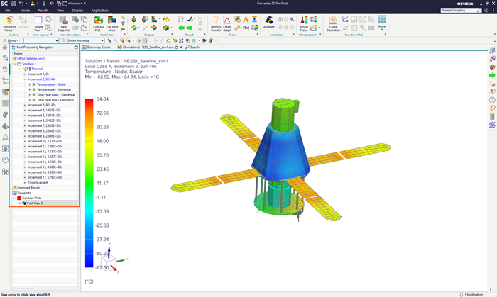
- Model file structure
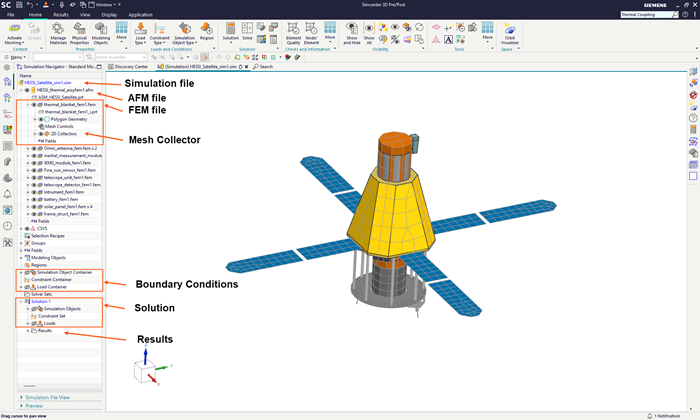
- A CAE model contains all data required to perform an analysis. In Simcenter 3D, the simplest CAE model consists of two primary files:
- The Simulation file (.sim), which contains loads, constraints and solver-specific data.
- The FEM (.fem), which contains meshes, physical, and material properties.
Depending on the workflow, the model may also reference:
- The idealized part file, which contains geometry that you can modify for your analysis.
- The master part file, which contains original CAD geometry.
The following diagram shows the relationship between the simulation, FEM model, idealized representation, and the master part, and how each level is reflected and managed within the Simulation Navigator.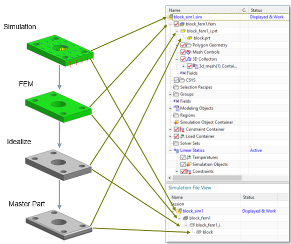
- Model orientation and display
- To orient the model, use standard, isometric, and trimetric views, as well as dynamically rotate, zoom, and pan the model by right-clicking the background of the graphics window.
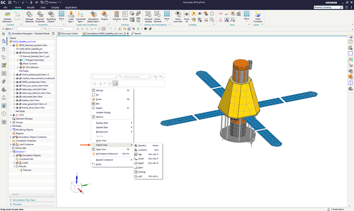
To change the rendering of your model based on materials, shading, and edge geometry, use the commands on the Display tab.
- Selection techniques
- You can use several object selection methods when working with complex models, including:
- QuickPick to select objects in crowded areas.
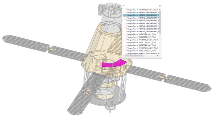
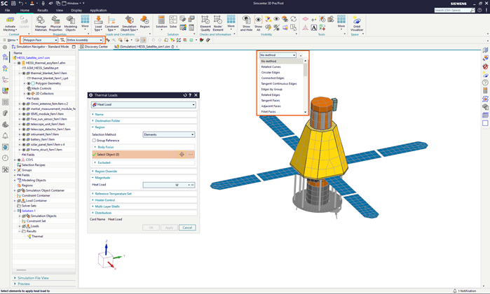
- Advanced selection options from the Top Border bar as shown to select objects by filtering them for specific attributes.
- Selection Recipes to select one or more finite element or geometric entities based on a set of rules.
- Groups to select subsets of geometric or finite element entities.
- QuickPick to select objects in crowded areas.
Hands-on material
To gain experience with the topics discussed here, complete the following: