Create the mesh mating conditions and mesh controls
Practice following workflow for connecting meshes using the Mesh Mating Conditions command and control the mesh density using the Mesh Controls command.
Open the part file
Open the part file and reset the dialog box settings.
- Choose File→Open and open power_supply\power_supply_x_t.prt.
- Choose File→Preferences→User Interface and on the Dialog and Precision page, reset the dialog box memory.
Create the FEM file
Create the FEM file using available templates in the Simcenter 3D software. For this activity, you will select the Simcenter 3D Electronic Systems Cooling template. Same procedure can be used for the Simcenter 3D Thermal/Flow and Simcenter 3D Space Systems Thermal templates.
-
Choose Application tab→Simulation group→Pre/Post
 .
.
- In the Simulation Navigator, right-click the power_supply_x_t.prt node and choose New FEM.
- From the Templates list, select Simcenter 3D Electronic Systems Cooling and click OK.
- To see all templates, choose File→Preferences→Solver Preferences, select All, and click OK.
- In the Solver Environment group, select Coupled Thermal-Flow as the analysis type.
- Click OK.
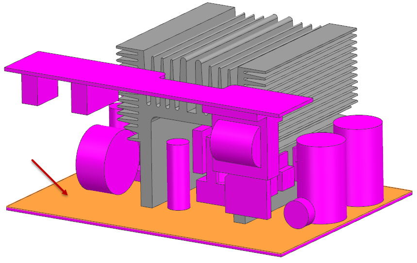
Create mesh for PCB panel
Generate a 3D swept mesh on the PCB panel and assign the material.
-
Choose Home tab→Mesh group→3D Swept Mesh
 .
.
- Select the Multi Body-Infer Target type.
-
In the graphics window, select the main PCB panel.
- In the Source Mesh Parameters group, in the Source Element Size box, specify 5 mm and click OK.
- In the Simulation Navigator, expand 3D Collectors, right-click Solid(1), and choose Edit.
-
In the Material group, click Choose
material
 and select
Polycarbonate.
and select
Polycarbonate.
- Click OK in all dialog boxes.
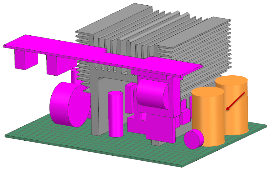
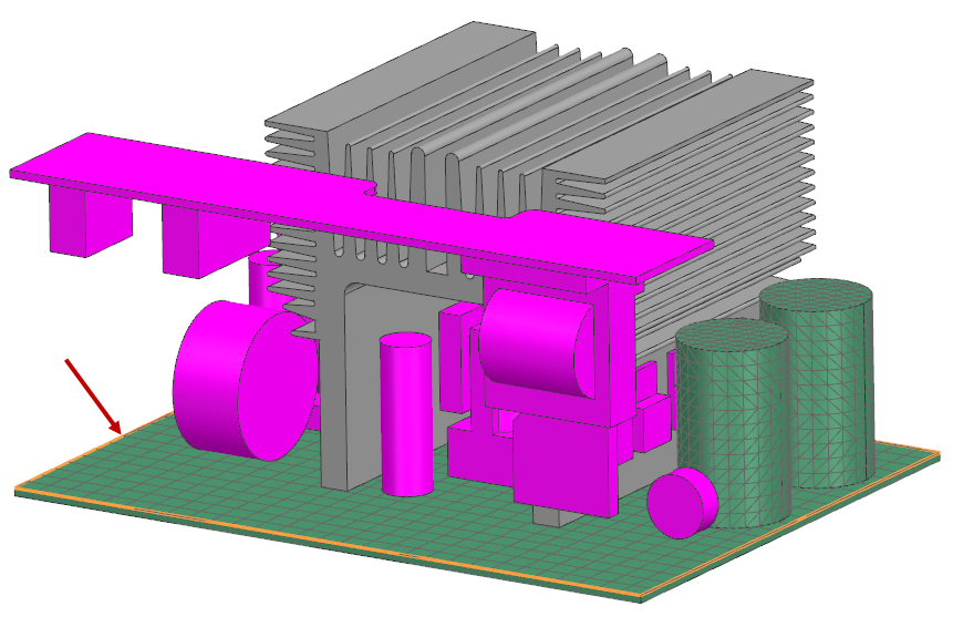
Create mesh for input filter capacitors
Create tetrahedral mesh for the input capacitors and assign aluminum material.
-
Choose Home tab→Mesh group→3D Tetrahedral
 .
.
-
Select the input filter capacitors in the graphics window.
- In the Mesh Parameters group, in the Element Size box, enter 3 mm.
-
In the Mesh Collector row, click New
Collector
 .
.
-
Click Choose material
and select
Aluminum_2014.
- Click OK in all dialog boxes.
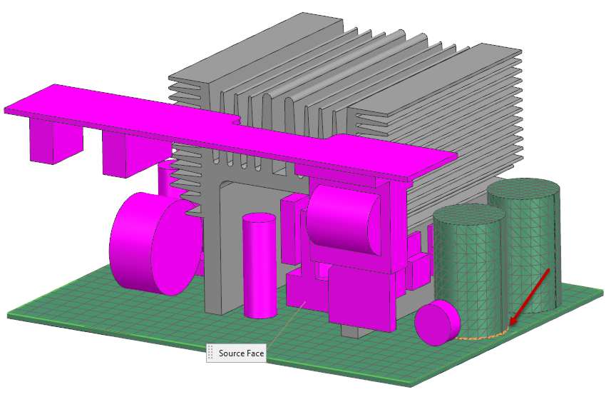
Connect meshes using mesh mating conditions
Manually define mesh mating conditions to connect adjacent meshes.
-
Choose Home tab→Connections group→Mesh Mating
 .
.
- From the Type list, select Manual Creation.
-
In the graphics window, select the source face.
-
Select the target face using the QuickPick tool if
needed.
- Click OK.
-
Choose Home tab→Context group→Update
 .
.
- Repeat steps to create mesh mating for the second input filter capacitor.
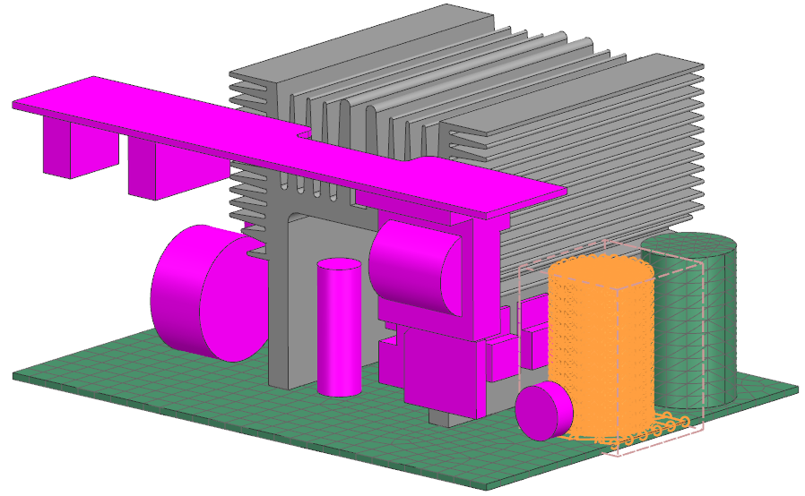
Control the mesh density using the Bounding Volume type mesh controls
Apply a localized mesh control using a bounding volume selection recipe.
- In the Simulation Navigator, right-click Selection Recipes and choose New Selection Recipe.
- Ensure Bounding Volume is selected in the Strategy list.
- Click Select All in the Entity Types group.
-
In Bounding Volume Definition, click CSYS
Dialog
 , then Point Dialog
 .
.
- Enter point coordinates: X = 47, Y = –33, Z = –100.
- Click OK twice.
- In the Dimensions group, set: Length = 30 mm, Width = 40 mm, and Height = 30 mm.
- In the Containment group, make sure Inside is selected.
-
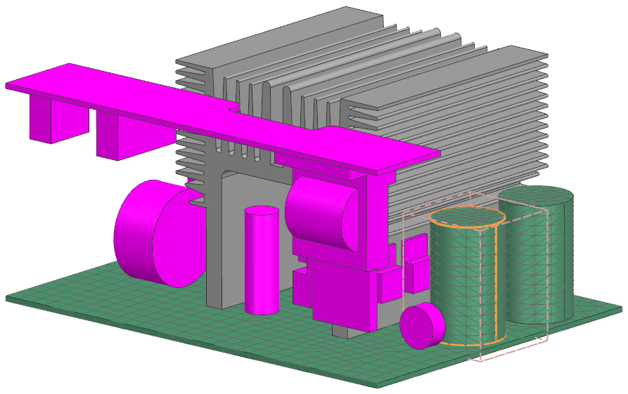
Click Show Result
 .
.
- Click OK.
-
Choose Home tab→Mesh group→Mesh Control
 .
.
- From the Type list, select Bounding Volume.
- In the Simulation Navigator, expand Selection Recipes and select the created one.
-
Click Select Target Polygon Bodies and the graphics
window, choose the indicated body.
- Click OK.
-
Choose Home tab→Context group→Update
.
The mesh now reflects the control.