Advanced meshing and assemblies
This lesson covers advanced meshing techniques, including primitives-based modeling, mesh controls, mesh quality improvements, and assembly-level meshing workflows.
This lesson may include hands-on exercises. Review the Discussion section for background information or click the button to proceed to the practical section.
Discussion
Advanced meshing techniques allow you to control mesh density, improve mesh connectivity, and refine existing meshes to support accurate and efficient thermal analyses.
- Controlling local mesh density
- Mesh density is controlled using the Mesh Control command, which allows you to refine or coarsen mesh sizes in specific regions of a model. Mesh controls help manage the number of elements in large models while ensuring sufficient resolution in areas where higher accuracy is required. They can be applied before or after mesh generation and support multiple control types.
- Mesh mating and mesh connectivity
- Mesh Mating conditions are used to connect individual 2D or 3D meshes at specified interfaces. They modify polygon body geometry to enforce common surface definitions and shared meshes where bodies mate. Mesh mating conditions are also used to resolve issues such as coincident nodes, which occur when duplicate nodes lie on top of each other at mesh interfaces.
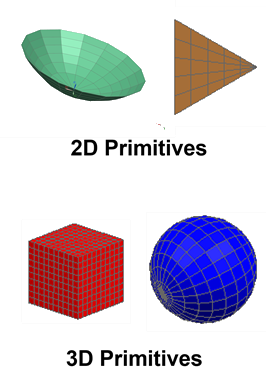
- Primitives-based modeling
-
A Primitive is an object that defines a set of 2D or 3D elements in terms of their geometry, size, location, and mesh. You can:
- Position and orient primitives using coordinate systems.
- Modify primitive geometry, size, and location after creation.
- Use primitives to efficiently model simplified or repetitive thermal features.
- Modeling assemblies with assembly FEMs
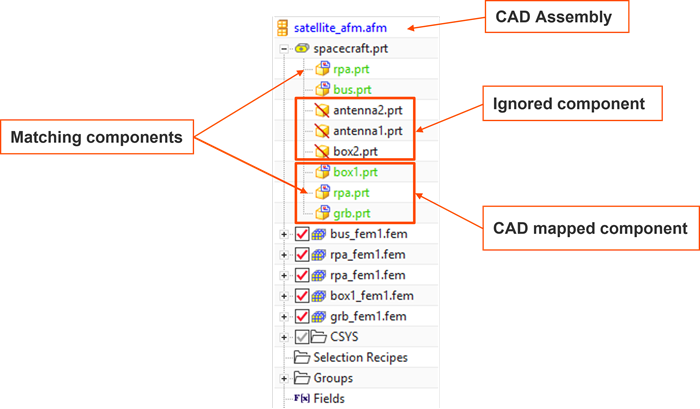
- Simcenter 3D Space Systems Thermal supports assembly-level analysis using an Assembly FEM (.afm) file.
Assembly FEMs are designed to efficiently model and analyze large systems
composed of multiple component FEMs.
When working with Assembly FEMs, you may encounter different component classifications, such as:
- CAD-mapped components.
- Ignored components.
- Matching or reused components.
Hands-on material
To gain experience with the topics discussed here, complete the following: