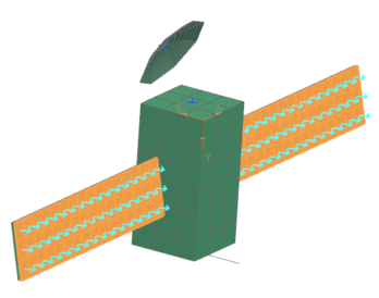
Build a model with primitives
Practice creating meshes using primitives, translating and reflecting existing elements. The starting FEM contains only 2D mesh collectors, no geometry or mesh.
Open the FEM file
Open the FEM and reset the dialog box settings.
- Choose File→Open and open primitives/primitivessat.fem.
- Choose File→Preferences → User Interface and on the Dialog and Precision page, reset the dialog box memory.
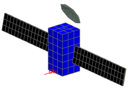
Create the bus
Create a box of 1 x 1 x 2 m and 3 mesh element divisions, per meter, to model and mesh the bus geometry.
- Choose Menu → Insert → Primitive → Box.
- In the Object Name box, type bus mesh.
- Clear the Automatic Creation check box in the Destination Collector group.
- From the Mesh Collector list, verify that bus collector is selected.
-
In the Definition group, click Construct
New Coordinate System
 .
.
-
From the Coordinate System list, choose
Absolute CSYS
 .
.
- In the Maximum Y box, enter 2000 mm.
-
In the Mesh Density group, specify the following
values:
- Along X = 3
- Along Y = 6
- Along Z = 3
- Click OK.
Create the right sun side solar panel
Create a rectangle of 3.5 m by 0.8 m and 16 x 3 mesh element divisions representing the side of the right solar panel pointing toward the Sun.
- Choose Menu → Insert → Primitive → Rectangle.
- Type sun side panel mesh in the Object Name box.
- Clear the Automatic Creation check box.
- From the Mesh Collector list, select sun side panel collector
-
In the Definition group, click Construct
New Coordinate System
.
-
From the Coordinate System list, choose
Absolute CSYS
.
-
Specify the following values to define the rectangle:
- Minimum X=1.22 m
- Maximum X=4.75 m
- Minimum Y=0.6 m
- Maximum Y=1.4 m
- Offset in Z=0.525 m
- In Mesh Density, specify Along X = 16 and Along Y = 3.
- Click OK.
Create the right dark side solar panel
Create the back side of the right solar panel by translating the previously created mesh, and move it to the appropriate mesh collector. You will offset the copy a distance of 50 mm in the global -Z direction.
-
Choose Nodes and Elements tab →
Elements group → Translate
 .
.
- From the Type list, select Non-associative Translate
- In the Element Type group, from the list, verify that Any Element is selected.
- In the graphics window, select all 48 panel elements
- In the Distance group, set DX = 0, DY = 0, DZ = –50 mm .
- Click OK.
- In the Simulation Navigator, expand the 2D Collector node, under the sun side panel collector node, select the sun side panel mesh_translate(1) node and drag it into the dark side panel collector node
- Click Keep Settings.
- Rename the mesh to dark side panel mesh.
Create the left solar panels
Rotate all the nodes from the right panel meshes 12 degrees in the -X direction, and then create a symmetric copy of the panels on the other side of the bus. You need also to create a reflection point, which is located at 500, 0, 500.
-
Choose Nodes and Elements tab →
Nodes group → Rotate
 .
.
- From the Type list, verify that Rotate is selected.
- In the graphics window, select all 136 panel nodes.
-
In the Axis of Rotation group, from the
Specify Vector list, select
–XC-axis
 .
.
-
In the Specify Point row, click Point
Dialog
 and enter: X = 1200 mm,
Y = 1000 mm, Z = 500
mm.
and enter: X = 1200 mm,
Y = 1000 mm, Z = 500
mm.
- Click OK.
- In the Rotation Angle group, enter rotation angle = 12°.
- Click OK.
-
Choose Nodes and Elements tab →
Tools group → Point
 .
.
- In the Output Coordinates group, specify the following values in the absolute coordinate system of the work part: X = 500 mm, Y = 0, Z = 500 mm.
-
Click OK.
The point is created in the middle of the top face of the bus.
-
Choose Nodes and Elements
tab→Elements group→More
list→Reflect
 .
.
- In the graphics window, select panel meshes.
-
In the Reflection Plane group, from the
Specify Plane list, select Point and
Direction
 .
.
- In the graphics window, select the created point and the X axis.
-
In the Specify Plane row, click Reverse
Direction
 such that the direction is
-X.
such that the direction is
-X.
-
Select the Preview check box.
- Click OK.
Create the antenna
Create a paraboloid of 0.15 m height and 0.6 m focal length. Use 8 elements in each direction. You will also move the antenna in XYZ (500 mm, –700 mm and 1000 mm), reflect it, and, finally, tilt it 30 degrees in the X direction.
- Choose Menu → Insert → Primitive → Paraboloid.
- Enter antenna mesh in the Object Name box.
- In the Destination Collector group, clear Automatic Creation.
- From the Mesh Collector list, choose antenna collector
-
In the Definition group, click Construct
New Coordinate System
.
-
From the Coordinate System list, choose
Absolute CSYS
.
-
Specify the following values to define the rectangle.
- Height = 0.15 m
- Focal Length = 0.6 m
-
In the Mesh Density group, specify:
- Along Circumference=8
- Along Height=8
- Select the Top side faces inward check box to reverse the direction of the surface normals of the 2D elements so that they point inward..
- Click OK.
-
Choose Nodes and Elements tab→Nodes
group→Translate
 .
.
-
In the graphics window, select all 65 antenna nodes.
Tip: For easier selection, hide the bus collector node.
- In the Translation Method group, specify: DX = 500 mm, DY = –700 mm, DZ = 1000 mm.
- Click OK.
-
Choose Nodes and Elements tab→Nodes
group→More
list→Reflect
 .
.
- In the graphics window, select all 65 antenna nodes.
-
In the Reflection Plane group, from the
Specify Plane list, select Point and
Direction .
- In the graphics window, select the center point of the antenna and the Z axis.
-
In the Specify Plane row, click Reverse
Direction
such that the direction is
-Z.
- Click OK.
-
Choose Nodes and Elements tab→Tools
group→Point
.
- Select the center node of the antenna.
- Click OK.
-
Choose Nodes and Elements tab→Nodes
group→Rotate
.
- In the graphics window, select all 65 antenna nodes.
-
In the Axis of Rotation group, from the
Specify Vector list, select XC-axis
 .
.
-
From the Specify Point list, select
Existing Point
 .
.
- In the graphics window, select the center point of the antenna.
- In the Rotation Angle group, in the Angle box, type 30 °.
-
Click OK.
Create a small antenna
Model a small antenna as a 1D element. You will first create a node at [333, 2000, -500], then use the node to create a 1D element joint to the closest node on the bus.
-
Choose Nodes and Elements tab→Nodes group→Node Create
 .
.
- In the Location group, specify: X = 333 mm, Y = 2000 mm, Z = –500 mm.
- Click OK.
-
Choose Nodes and Elements tab →
Elements group → Element
Create
 .
.
- From the Element Family list, select 1D.
- In the graphics window, select the previously created node and its closest node on the bus.
- Click Close.
- In the Simulation Navigator, expand the 1D Collectors→Beam(1) nodes.
- Rename the Beam(1)node to small antenna collector.
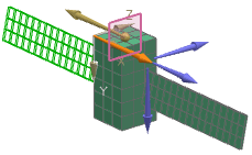
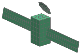
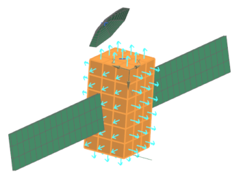
Check normals and change mesh colors
Validate normal directions and apply display colors to mesh collectors for clarity and setup. The element normal direction determines the top and bottom sides of a mesh. Thermo-optical properties can be independently defined for both sides
- In the Simulation Navigator, right-click the sun side panel collector and choose Check All → Element Normals.
-
Click Display Normals.
The normals should point outward from the geometry as shown.
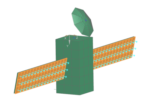 Ensure normals point outward. If needed, click Reverse Normals.
 -
Verify normals for dark side panel and bus meshes.
- Click Close.
- In the Simulation Navigator, right-click antenna collector → Edit Display.
- In the Display group, select the Color swatch, and then select Iron Gray (ID = 201) in the color palette.
- Click OK.
-
Verify that, in the front of Color, Apply
Changes
 is displayed.
If it is not displayed, click next to Color and select Apply Changes.
is displayed.
If it is not displayed, click next to Color and select Apply Changes. - Click OK.
-
Repeat for other collectors: small antenna (186), bus (211), dark side
panel (216), sun side panel (125).