Automate meshing with selection recipes and template files
Learn how to use selection recipes together with template files to automate tasks required to mesh a finite element model.
Open the part file
Open the part file.
- Choose File→Open and open selection_recipe/wing.prt.
- Choose File→Preferences→User Interface and on the Dialog and Precision page, reset the dialog box memory.
- Click OK.
-
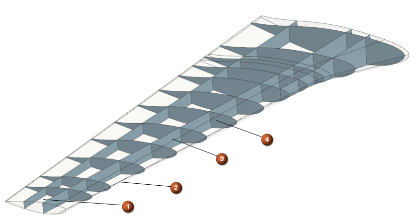
Explore the model that contains the following shells:
- 1 - upper surface
- 2 - lower surface
- 3 - longitudinal reinforcements
- 4 - lateral reinforcements
Define attributes in the part file
Define material and thickness attributes of the structure.
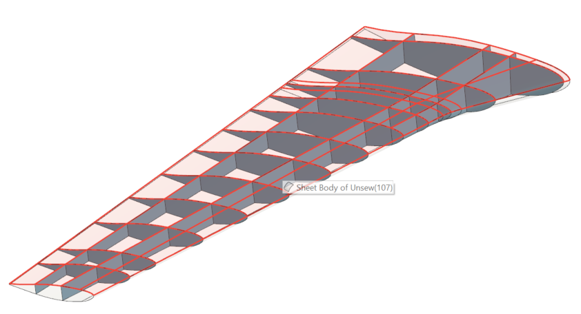
- In the Top Border bar, from the Type Filter list, select Sheet Body.
- In the graphics window, select the whole model, right-click and select Properties to define attributes.
- In the Context group, from the Interaction Method list, select Traditional.
- In the Sheet Body Attributes group, make sure Data Type is set to String.
- In the Title/Alias box, type MAT.
-
In the Value, type
7075P6.
This is the name of the material that you will create later in the FEM file.
-
Click Add New Attribute
 .
.
- In the Data Type list, select Number to create the numeric type of attribute which will allow defining the thickness.
- In the Title/Alias box, type THICKNESS.
- In the Value, type 10.
-
Click Add New Attribute
.
- Click OK.
-
In the graphics window, right-click the upper surface as shown in the
following image and select Properties to set a
different material attribute for the upper surface.
- In the Sheet Body Attributes group, click MAT and in the Value box, type 2024T3.
- Click OK.
Create a FEM file
Create a FEM file and verify the inherited attributes.
-
In the Application tab, in the
Simulation group, click
Pre/Post
 .
.
- In the Simulation Navigator, right-click the wing.prt node and select New FEM.
- In the Templates group, select one of the following solvers: Simcenter 3D Multiphysics, Simcenter 3D Electronic Systems Cooling, Simcenter 3D Thermal/Flow, and Simcenter 3D Space Systems Thermal. For this activity, the Simcenter 3D Multiphysics solver is used.
- In the New File Name group, in the Name box, type wing_template.fem.
-
Next to Folder, click
 to browse to the folder where the part file is
saved.
to browse to the folder where the part file is
saved.
- Click OK.
-
In the CAD Part group, from the Polygon
Body Resolution, select High to
create the polygon geometry using the highest level of tessellation.
This option is useful for parts in which you want to capture the curvature of edges and faces very accurately.
- In the Solver Environment group, from the Analysis Type list, select Coupled Thermal-Flow.
- Click OK.
- In the Top Border bar, from the Type Filter list, select Polygon Body.
- In the graphics window, right-click the body and select Properties to verify if the attributes have been inherited from the part file.
- Rotate the model and verify the attributes on the lower surface of the structure.
- Click Cancel.
Create the selection recipes
Create the selection recipes based on the attributes that you previously defined.
- In the Simulation Navigator, right-click the Selection Recipes and select New Selection Recipe to create a selection recipe which is based on thickness and 2024T3 MAT attributes.
- In the Type group, from the Strategy list, select Attribute.
- In the Name box, type 10mm_2024T3.
- In the Entity Types group, from the Entity Type list, select Polygon Body.
-
In the Attributes group, from the Attribute list, select User Attribute and click Add Attribute
 .
.
- In the User Attribute sub-group, from the Type list, select String.
- In the Title/Alias box, type MAT.
- In the Low String Value, type 2024T3.
-
Select the Preview check box.
Notice that in the graphics window the upper surface is highlighted where the 2024T3 MAT attribute is assigned.
- In the Attributes group, click Add Attribute to add the THICKNESS attribute.
- In the User Attribute sub-group, from the Type list, select Number.
- In the Title/Alias box, type THICKNESS.
- In the Low Real Value, type 10.
- Click OK.
- In the Simulation Navigator, expand the Selection Recipes node, right-click the 10mm_2024T3 node and choose Clone to create the second selection recipe based on thickness and 7075P6 MAT attributes.
- In the Name box, type 10mm_7075P6.
- In the Attributes group, select MAT.
- In the Low String Value, type 7075P6.
- Click OK.
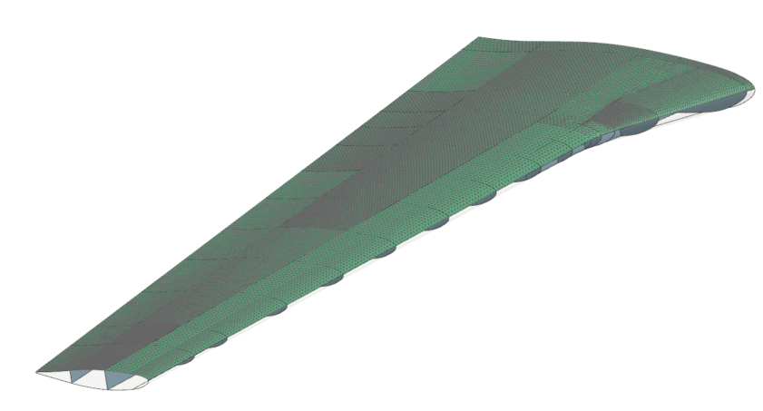
Create the meshes
Create meshes for upper and lower surfaces using the selection recipe that facilitates the selection of the surfaces.
-
Choose Home tab→Mesh
group→2D Mesh
 to create the mesh for the upper
surface.
to create the mesh for the upper
surface.
- In the Mesh Name box, type 10mm_2024T3.
- In the Top Border bar, from the Type Filter list, select Selection Recipe.
- In the Simulation Navigator, under the Selection Recipes node, select 10mm_2024T3.
- In the Element Size box, type 25.
-
Click OK.
-
Choose Home tab→Mesh
group→2D Mesh
to create the mesh for the rest
of the model.
- In the Mesh Name box, type 10mm_7075P6.
- In the Simulation Navigator, under the Selection Recipes node, select 10mm_7075P6.
- Click OK.
Create materials and assign them to the corresponding collector
Create material named 2024T3 and 7075P6.
- In the Simulation Navigator, expand the 2D Collectors node, right-click the Shell(1) node and choose Edit.
-
In the Properties group, click
Edit
 .
.
- In the Thickness group, in the Thickness box, type 10.
-
In the Material sub-group, next to
Material 1, click Choose
material
 .
.
-
In the Material List group, next to
Create, click Create
material
 .
.
-
In the Name - Description group, type
2024T3.
If desired, you can assign any properties to the material.
- Click OK in all dialog boxes.
- Repeat steps 1-7 to create the 7075P6 material and assign material and thickness to the Shell(2) collector.
Disconnect the FEM and CAD files
Break the association between the FEM and the selected CAD source part to use the FEM file as a template.
- In the Simulation Navigator, right-click the wing_template.fem node and choose Replace Ideal/Master Part.
- In the CAD Part group, clear the Associate to Master Part check box to break the link between the CAD and FEM file.
- Click OK.
- Click Continue without a log.
-
In the Simulation Navigator, observe that the
selection recipes are empty, because there is no polygon geometry to which
it was attached and meshes contain 0 elements.
This structure you will save in the FEM file and will use as a template in Simcenter 3D.
- Choose File→Save→Save All to save the FEM and part files.
- Close the software.
Add a custom template file to a .pax file
For CAE applications, template files contain the settings and the FE modeling definitions that you need to define an analysis. The .pax file is an XML file that defines the FEM and Simulation file templates that the software loads automatically when you create a new part file with a template. You will customize the .pax file by editing the XML content with a text editor to add entries that point to your own custom template file.
- Browse to the selection_recipe folder and move the wing_template.fem file to the Template folder.
- In the Template folder, edit the Templates_SC.pax file using the text editor.
-
Edit the
<Filename>attribute to point to the wing_template.fem file. -
Edit the
<Presentation>name toWing Template Simcenter Thermal/Flow Fem.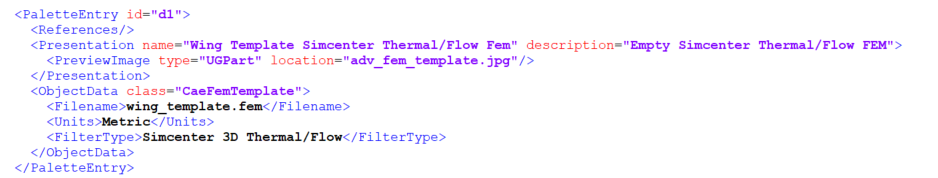
- Explore the definitions for the simulation file template. Notice the title of the simulation template.
- Save the Templates_SC.pax file.
Change the templates folder directory
Redirect the default template directory to your current working folder to avoid modifying the default templates.
- Click Windows Start.
- Type env in the Windows search box and select Edit environment variables for your account.
- Create a new variable called: UGII_TEMPLATE_DIR.
- Set its value to the .../selection_recipe/Template folder.
- Click OK to all windows.
- Start the software.
Create a new FEM file using the template
Create a new FEM using the customized template.
- Choose File tab→New.
-
In the Templates group, from the list, select the
Wing Template Simcenter Thermal/Flow Fem
template.
Notice, that this is the title that you modified in the .PAX file.
- In the New File Name group, in the Name box, type wing_fem1.fem.
- Next to Folder, browse to the selection_recipe folder.
- Click OK.
- In the CAD Part group, select the Associate to Master Part check box.
-
Next to Part, click Open Part
 and select the wing.prt
file.
and select the wing.prt
file.
-
Click OK in all dialog boxes.
The software automatically uses the selection recipes in the template to select geometry that meets the specified criteria and generates meshes using the parameters in the template file.
- Optionally, you can create a Simulation file using the Wing Template Simcenter Thermal/Flow Sim template that already contains the defined boundary conditions by right-clicking the wing_fem1.fem node and selecting New Simulation.
Remove the user defined templates
Remove the UG template environmental variable from the system to return to the preset templates. For other activities or your daily work you may not need the templates you defined.
- Click Windows Start.
- Type env in the Windows search box and select Edit environment variables for your account.
- Select UGII_TEMPLATE_DIR.
- Click Delete.
- Click OK twice.
- Restart the software for your next labs.