Create an assembly FEM and mesh components
This is an objective-based lab. Instead of being provided a list of instructions, you are simply provided a scenario and problem statement to solve. Please work to solve the scenario of each activity listed below.
Scenario:
You are given a satellite assembly with multiple subassemblies and components some with multiple instances. Some of the subassemblies and components are already meshed in their respective FEMs. You are asked to prepare the assembly for a thermal analysis by creating the assembly FEM, associating all instances of the subelements and components to existing FEMs, and creating FEM for the solar panel.
The solar panel material is aluminum, which you can model using the the Aluminum_6061 material. It is made of two 1 mm thick layers where the top facesheet has the values of emissivity equal to 0.02 and absorptivity equal to 0.04, and the bottom facesheet has the values of emissivity equal to 0.85 and absorptivity equal to 0.82. The coupling between the two layers can be modeled using the heat transfer coefficient of 2 W/(m2·°C) and effective emissivity of 0.067 accounting for conduction and radiation.
Questions:
How to prepare a satellite assembly FEM, create the solar panel FEM, map it to the assembly FEM, and mesh the solar panels for a thermal analysis?
Instructions:
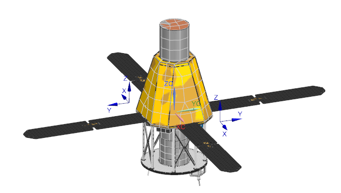
- In the satellite_assembly folder, open the ASM_Hessi_Satellite.prt file and explore the satellite assembly.
-
Create a new assembly FEM in the Simcenter 3D Space System
Thermal environment.
Notice that in Simcenter Navigator, under the ASM_Hessi_Satellite.prt node, the status for all its components is Ignored, because you did not add them to the assembly FEM.
-
All necessary FEMs are provided except the solar panel FEM. Using the
information from the provided table, associate all instances of the
subassemblies and components with their existing FEMs using the Map
Existing command.
Table 1. Subassembly and FEM Mapping Subassembly/Component FEM Comments Frame structure subasm frame_struct_fem1.fem Map FEM Solar Panels Create FEM Battery battery_fem1.fem Map FEM Instrument Data Processing Unit Instrument Data Processing Unit FEM.fem Map FEM Solid-State Recorder Unit Ignore for thermal analysis Telescope Detector Unit telescope_detector_fem1.fem Map FEM Telescope Unit telescope_unit_fem1.fem Map FEM Fine SunSensor Unit Ignore for thermal analysis IEMS Module IEMS_module_fem1.fem Map FEM Inertial Measurement Module inertial_measurement_module_fem1.fem Map FEM Solid-State Recorder Unit Case solid_state_recorder_fem1.fem Map FEM Omni_antenna Omni_antenna_fem.fem Map FEM Thermal_protection_blanket thermal_blanket_fem1.fem Map FEM attachment_connector Ignore for thermal analysis 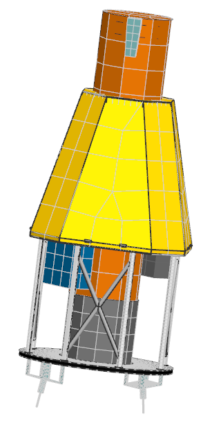
Because most of the other components are not required for the thermal analysis, you will not mesh them and their status will stay Ignored in the Assembly FEM.
-
The Solar Panels.prt file does not have an associated FEM. Associate the solar panel part file with a new FEM that you create using the Simcenter 3D Space System Thermal template. Make sure to find all matching components.
- In the new solar panel FEM, mesh the bottom faces of the solar panel, for example, using the QUAD4 Thin Shell mesh type with an element size of 126 mm.
-
For the shell mesh collector, create a Multi-Layer Shell
Non-Uniform physical property with the two stack layers:
- Top facesheet has the Aluminum_6061 material and 1 mm thickness with the top advanced thermo-optical properties having emissivity of 0.02 and absorptivity of 0.04.
- Bottom facesheet has the same material and thickness as the top facesheet with the bottom advanced thermo-optical properties having emissivity of 0.85 and absorptivity of 0.82. Couple the bottom to top layers with the following specified coupling magnitude, accounting for conduction and radiation: the heat transfer coefficient of 2 W/(m2·°C) and effective emissivity of 0.067.
-
In the parent assembly FEM, check for label conflicts and resolve them in the
Assembly Label Manager dialog box.
The assembly model is now meshed. You will apply boundary conditions and analyze the model in the next lab.