Card 5a - Element
This optional card defines the elements from which TMG calculates conductive, convective, and radiative conductances and hydraulic resistances.
Parameters: N, TYPE, MAT,
FRONTOPTPROP, PROP, NODE1,
NODE2,….
N
N is the element number, 1 ≤ N ≤ 9999999.
TYPE = SURFACE
TYPE = SURFACE specifies that a lump mass, beam, or planar
element.
= On is a special type of SURFACE element, where the reverse side
optical properties are defined on Card 9 OPTICAL (e.g. O10). The front side surface
properties may be defined with an OPTICAL Card ID in the FRONTOPTPROP field.
TYPE = SOLID
TYPE = SOLID (or –9) specifies that it is a solid tetrahedron,
wedge, or hexahedron. The COND module calculates capacitances and conductances to
adjacent solid and planar elements when using the finite volume method.
TYPE = MIDSIDE
TYPE = MIDSIDE (or –11) specifies that the element is parabolic and
lists the midside nodes. The MAT, FRONTOPTPROP, PROP and MAT fields are ignored.
TYPE = NONTHERM
TYPE = NONTHERM (or -12) specifies that the element will not take
part in the thermal calculations, but can be referenced as a characteristic element
for Card 6e free convection options.
TYPE = FLOWSEC
TYPE = FLOWSEC (or –2450)
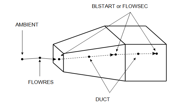
A 1-node FLOWSEC element defines a duct cross–sectional area, hydraulic diameter, and fluid properties at its location. FLOWSEC elements are automatically created at the ends of 2-node hydraulic elements that do not have one specified. At free ends, AMBIENT elements are created.
If MAT and PROP fields are set to 0, the material properties are set to those of the immediately upstream 1–node hydraulic element. Thus FLOWSEC properties are propagated downstream until a new FLOWSEC or BLSTART element is encountered.
A FLOWSEC or BLSTART element must be specified wherever 3 or more 2-node hydraulic elements meet.
FLOWSEC elements may not be referenced on Card 6e NEARCx convective thermal couplings.
TYPE = BLSTART
TYPE = BLSTART (or –2451) is similar to a FLOWSEC element, but it
also defines the start of the boundary layer for the downstream hydraulic elements.
A BLSTART element is useful for calculating heat transfer coefficients for a flat
plate in free stream (Card 6e NEARC4) or duct flow with boundary layer (Card 6e
NEARC12).
TYPE = AMBIENT
TYPE = AMBIENT (or –2452) defines temperature and pressure boundary
conditions with values are specified on the HYDENV Card. These values may be updated
through table interpolation or a user–written subroutine.
A 1-node AMBIENT element specifies the properties of the ambient fluid. There must be at least one AMBIENT element present in a hydraulic model.
AMBIENT elements can act as inlets or exhausts to hydraulic networks. The area and hydraulic diameter are very large, hence the computed velocities and dynamic pressures will be near zero.
The PROP field is ignored for AMBIENT elements.
TYPE = DUCT
TYPE = DUCT
(or –2000)
For 2-node DUCT elements TMG computes length–dependent flow resistances.
A DUCT element may be a straight duct, or a diffuser or a nozzle if it has different cross-sectional areas at its ends. A flow resistance multiplier may be specified on the PROP Card to model roughness effects.
The pressure–flow relationship for a FLOWRES or a DUCT element is defined by:
where:
- DELTAPT is the total pressure drop over the 2–node element, > 0 when the total pressure at NODE1 is > than the total pressure at NODE2.
- V is the flow velocity at the narrower end.
- ρ is the fluid density at the narrower end.
- MASSFL is the mass flow through the element.
- RESIJ is the hydraulic flow resistance computed for a smooth duct.
- KLOSS = R⋅K⋅KTABLE is the head loss factor.
- KTABLE is the table-dependent hydraulic flow resistance multiplier specified on the PROP Card (default = 1).
- R is the head loss factor computed for fully developed flow in a smooth duct.
- K is a head loss factor multiplier specified on the PROP Card (default = 1).
- The MAT field is ignored for DUCT elements.
TYPE =
                    FLOWRES
TYPE =
FLOWRES (or –2002) is similar to a DUCT element, except that the
computed flow resistance is length–independent. R = 1 for a FLOWRES element in the
above equation.
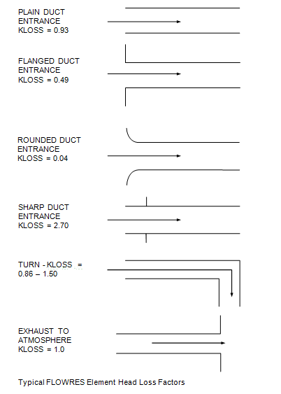
FLOWRES elements may be used to model losses over elbows, exits, entrances, and orifices.
Exit and entrance total pressure drops may be modeled with either FLOWRES or DUCT elements. The difference is that for FLOWRES elements the KLOSS factor is totally specified on the PROP Card, while for DUCT elements it is automatically calculated whenever if an abrupt area change is encountered. Some typical KLOSS values are presented below (see images below). The MAT field is ignored for FLOWRES elements.
TYPE =
                    FANPUMP
TYPE =
FANPUMP (or –2003)
A FANPUMP 2–node hydraulic element is used to specify a flow boundary condition such as total pressure rise, mass flow, volumetric flow, and flow velocity. These values are specified on the PROP Card.
The outlet is at defined at NODE1, inlet is at NODE2.
The MAT field of a FANPUMP element is ignored.
The total pressure rise boundary condition DELTAPT over a FANPUMP element is modeled with:
where:
- K is a multiplier defined on the PROP Card
- KTABLE is a value interpolated from the table specified on the PROP Card. For this table, the dependent variable code on the Card 9 TABTYPE Card must be DELTAPT.
- DELTAPT is considered > 0 when the total pressure at the inlet is lower than the one at the outlet. Note that this definition is the opposite of the one adopted for the FLOWRES and DUCT elements.
The mass flow boundary condition through a FANPUMP element is modeled with:
The dependent variable code on the TABTYPE Card must be MASSFL. The mass flow is considered positive if it flows from inlet to outlet.
The volumetric flow rate boundary condition VOLUME through the element is modeled with:
The dependent variable code on the TABTYPE Card must be VOLUME. Volumetric flow rate is considered positive if it flows from inlet to outlet.
The velocity boundary condition at the narrower end of the FANPUMP element is modeled with:
The dependent variable code on the TABTYPE Card must be VELOC. Velocity is positive if it flows from NODE1 to NODE2.
TYPE = FLOWCON
TYPE = FLOWCON (or –2450)
A 1-node FLOWCON element defines a stream fluid properties at its location. FLOWCON elements should be created at all nodes referenced in the STREAM elements, including the free ends. Though a FLOWCON element is defined synonymously to a FLOWSEC element, it is distinguished by that its PROP field should always be defined (not set to 0) and should reference a valid FLOWCON PROP card instead of a FLOWSEC one.
If the MAT field is set to 0, the material properties are set to those of the immediately upstream 1–node hydraulic element.
TYPE = STREAM
TYPE = STREAM (or –2003)
A 2-node STREAM element is used to either specify a mass flow boundary condition or to simply define the fluid flow path (inter-node connections) in the stream network, depending on the PROP card used. A STREAM element is synonymous to a FANPUMP hydraulic element except that it references a STREAM PROP card, which is similar to a FANPUMP PROP card except that it can only have either a mass flow definition (not total pressure rise, volumetric flow, or flow velocity) or no flow boundary condition at all. The outlet is defined at NODE1 and the inlet is at NODE2. The MAT field of a STREAM element is ignored.
MAT
MAT may be 0, or a mnemonic of the form Mm (e.g., M10), where m is a
material property id of a Card 9 MAT Card.
For non–hydraulic elements MAT = 0 defaults to the default material
properties.
For hydraulic elements MAT = 0 defaults to the properties of the
immediately upstream 1–node hydraulic element.
FRONTOPTPROP
FRONTOPTPROP may be 0 or a mnemonic of the form On (e.g. 010), where
n is an optical property number referencing a Card 9 OPTICAL.
If FRONTOPTPROP is 0 and TYPE is SURFACE, then the optical surface properties are taken form the Card 9 MAT specified in the MAT field.
PROP
PROP may be 0 or a mnemonic of the form Pp (e.g., P12), where p is a
physical property number referencing a Card 9 PROP.
A PROP Card is mandatory for SURFACE, FLUID, DUCT, FANPUMP, FLOWRES, FLOWCON, and STREAM elements.
Code example
RTEST667 CARD 5A EXAMPLE - FLOW IN A SINGLE CHANNEL
-1
3 0 0 0 0 0 0 0 0 0 0   $ CARD 2A M=1+2 - VUFAC +
$                       $ COND MODULES RUN
0 273 0 0 0 200
-1
-1
1 -.0254 0 0            $ AMBIENT NODE
2 0 0 0
11 1 0 0
12 1 .00254 0
13 1 .00254 .15
14 1 0 .15
3 .254 0 0
4 .30 0 0
5 .33 0 0
31 0 -.01 -.075
GEN 2 2 1 2 .254 0 0 0 0 .15
GEN3RD 2 10 0 .02 0
-1
$ CARD 5A ELEMENT DEFINITIONS
$
1 SURFACE M1 0 P1 31 32 34 33   $ BOARD ELEMENT 1
2 SURFACE M1 0 P1 41 42 44 43   $ BOARD ELEMENT 2
$
$ 1-NODE HYDRAULIC ELEMENT DEFINITIONS
$
3001 AMBIENT M2 0 P8 1     $ AMBIENT ELEMENT IS
$                          $ AT ENTRANCE
3003 FLOWSEC M2 0 P2 2     $ FLOWSEC ELEMENT AT
$                          $ BOARD INLET
9900 FLOWSEC M2 0 P2 3     $ FLOWSEC AT FAN INLET
3007 FLOWSEC M2 0 P3 4     $ FAN OUTLET AREA
3009 AMBIENT M2 0 P8 5     $ AMBIENT ELEMENT AT EXHAUST
$
$ 2-NODE HYDRAULIC ELEMENT DEFINITIONS
$
3002 FLOWRES 0 0 P4 1 2    $ ENTRANCE RESISTANCE
3004 DUCT 0 0 P5 2 3       $ DUCT BETWEEN CIRCUIT BOARDS
3006 FANPUMP 0 0 P6 3 4    $ FANPUMP
3008 FLOWRES 0 0 P7 4 5    $ EXIT RESISTANCE
$                          $ TO ATMOSPHERE
4000 0 M1 0 P1 11 12 13 14 $ QUAD ELEMENT DEFINES
$                          $ DUCT PROFILE
-1
$ CARD 6 CARD
$
$ FORCED CONVECTION CONDUCTANCES
$
AREA BOARDS 0 0 FLUID 0 1 NEARC1
-1
-1
-1
$ CARD 9 CARDS
$
NAME BOARDS 1 2             $ BOARD ELEMENTS GROUP NAME
NAME FLUID 3001 3009        $ FLUID ELEMENTS GROUP NAME
HYDENV 101351 20 9.81 180 0 $ ENVIRONMENT IN SI UNITS
TABTYPE 1 VOLUME TIME       $ CONSTANT VOLUME FAN
TABDATA 1 .002 0            $ SINGLE TABDATA CARD
QNODE BOARDS 20             $ BOARD DISSIPATION 20 W
PRINT 1 9999 TEMP           $ PRINTOUT CARDS
PRINT 1 9999 HFGROUP
MAT 1 KTHERM 0              $ MAT CARD FOR BOARDS
PROP 1 SHELL 0              $ PROP CARD FOR BOARDS
MAT 2 RHO 1.207             $ MAT CARD FOR FLUID
MAT 2 CPP 1007              $ MAT CARD FOR FLUID
MAT 2 KTHERM .0263          $ MAT CARD FOR FLUID
MAT 2 VISC 1.85E-5          $ MAT CARD FOR FLUID
$
$ MAT CARD FOR AMBIENT ELEMENTS
$
PROP 2 FLOWSEC 0 0 4000     $ PROP CARD FOR BOARD INLET.
$                           $ DUCT PROFILE DEFINED AT
$
$                           $ DUCT PROFILE DEFINED AT
$                           $ ELEMENT 4000
PROP 3 FLOWSEC .001         $ FAN OUTLET AREA = .001
PROP 4 FLOWRES .83          $ ENTRANCE RSISTANCE = .83
PROP 5 DUCT 2               $ DUCT RESISTANCE MULTIPLIER=2
PROP 6 FANPUMP 1 1          $ FANPUMP REFERENCES TABLE 1
PROP 7 FLOWRES 1            $ EXIT RESISTANCE 1.0
PROP 8 AMBIENT              $ AMBIENT PROP CARD
-1
-1
Notes
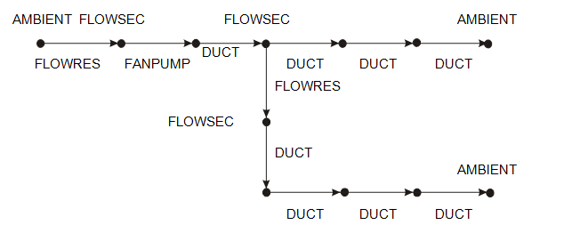
Hydraulic elements may be one–node FLOWSEC, BLSTART, or AMBIENT elements, or two–node DUCT, FLOWRES, and FANPUMP elements.
For 2–node hydraulic elements the COND module connects the element CG to its ends with equal flow resistances to model pressure drops and 1–way conductances to model heat transported by the fluid.
The nominal and initial flow directions are defined to occur in the direction from NODE1 to NODE2.
The environmental properties (standard temperature & pressure, gravity, AMBIENT element pressure & temperature) are specified on a Card 9 HYDENV Card.
Gravity value and direction specified on the HYDENV Card are used to calculate the buoyancy forces and free convection heat transfer coefficients. Buoyancy effects may be turned off with the Card 9 PARAM NOBUOY option.
Total pressure boundary conditions are specified on Card 9 PSINK Cards and on AMBIENT elements. Flow boundary conditions are specified on FANPUMP elements.
Convective heat transfer between surface elements and hydraulic elements is modeled with the Card 6e NEARCx options.
During each thermal steady–state iteration or transient time step, the complete hydraulic element network is solved in a separate iterative solution loop to determine pressure and mass flow. The convergence criterion for this iterative loop may be specified with a Card 9 PARAM PDMAX Card.